Intervertebral prosthesis with self-tapping fixing projections

a technology of fixing projections and intervertebral prostheses, which is applied in the field of intervertebral prosthesis with self-tapping fixing projections, can solve the problems of inability to work the cover plate of the cervical spine, inability to operate with a large amount, and inability to achieve the work of the cervical spin

Active Publication Date: 2010-07-29
CERVITECH INC
View PDF14 Cites 72 Cited by
  • Summary
  • Abstract
  • Description
  • Claims
  • Application Information

AI Technical Summary

Benefits of technology

[0005]The problem addressed by the invention is therefore that of making available an intervertebral prosthesis with self-tapping fixing projections which can be introduced into a secure fixing position even with just slight distraction of the vertebral bodies, without excessive damage to the cover plates of the vertebral bodies in the area lying ventrally of their fixing position.
[0007]Any irregularities in the bone surface, which would be planed away if the leading face of the ribs during implantation was steep and sharp, can slide across this surface onto the rib without damage or with only minimal damage. Measured in a plane extending parallel to the implantation direction, it should enclose an angle of less than 45° with the base surface. It is assumed here that the base surface extends approximately parallel to the main directions of the attachment plate. The slide-on surface can be smooth in order to offer little resistance and in order to cause the least possible damage to the bone surface. However, an embodiment is also advantageous in which the slide-on surface is roughened and for example provided with small teeth which, after implantation, connect intimately with the bone surface in order to obtain an additional fixing effect.
[0009]An embodiment is preferred in which the rib is interrupted a plurality of times in order to form a series of pointed or sharp teeth. This reduces the size of the cross-sectional surface area of the rib (in a sectional plane extending parallel to the surface extent of the prosthesis), which determines the resistance to penetration into the bone surface. This rib formed by teeth therefore penetrates more easily and more deeply into the bone surface than a continuous rib with a similar profile. If, according to a further feature of the invention, the interruptions extend transverse to the AP direction, they form additional surfaces which counteract a movement of the prosthesis in the ventral direction. These surfaces too should therefore be steep. The interruptions can be produced more easily if they extend parallel in all the ribs.
[0011]In another embodiment of the invention, the interruptions extend parallel to the implantation direction. The size of the edge acting with a scraping effect on the bone surface during implantation is thereby reduced. In this case, only the side faces of the rib extending obliquely with respect to the implantation direction from the resistance against the movement of the prosthesis in the ventral direction and from the slide-on surface on the dorsal face.
[0016]The height of the ribs above the base surface should be sufficient for secure engagement in the bone substance. It should generally not be less than 0.5 mm. Their height is limited by the aim of minimizing the distraction during implantation and the scraping off of the cover plates of the vertebral bodies by the fixing projections. It should generally not exceed 2 mm (preferably 1.6 mm) or one eighth (preferably one tenth) of the AP dimension of the attachment surface. A height of 0.7 to 1.5 mm has proven useful for cervical prostheses. The height is to be measured above the base surface, i.e. that surface surrounding the ribs which is expected to bear on the bone. If this surface has a roughness, for example a porous coating or an arrangement of rows of teeth substantially covering the whole surface area, with bone substance intended to grow into the gaps between the teeth over the course of time, the surface area of this roughness is a critical factor.

Problems solved by technology

Producing these requires deep working of the cover plates of the vertebral bodies, which entails considerable outlay in operating terms.
Such working of the cover plates of the vertebral bodies is also undesirable, and in the area of the cervical spine often impossible, because it demands considerable distraction and presupposes a substantial thickness of the vertebral bodies.
Although a displacement of the prosthesis in the ventral direction can normally be prevented by this means, cases nevertheless occur where, because of unusual anatomy or unsuitable surgical preparation, the intervertebral space opens out in such a pronounced wedge shape in the ventral direction that the prosthesis cannot be securely held in place by the toothing alone.
However, the known prostheses of this kind require considerable distraction to ensure that they are not impeded by the fixing projections when fitted into place.
If they were to be pressed in without sufficient distraction, the fixing projections would carve out channels in the cover plates of the vertebral bodies, and they could then slide out again through these channels, in addition to which the channels are undesirable because of the loss of strength they entail.

Method used


Image

  • Intervertebral prosthesis with self-tapping fixing projections
  • Intervertebral prosthesis with self-tapping fixing projections
  • Intervertebral prosthesis with self-tapping fixing projections

Examples


Embodiment Construction

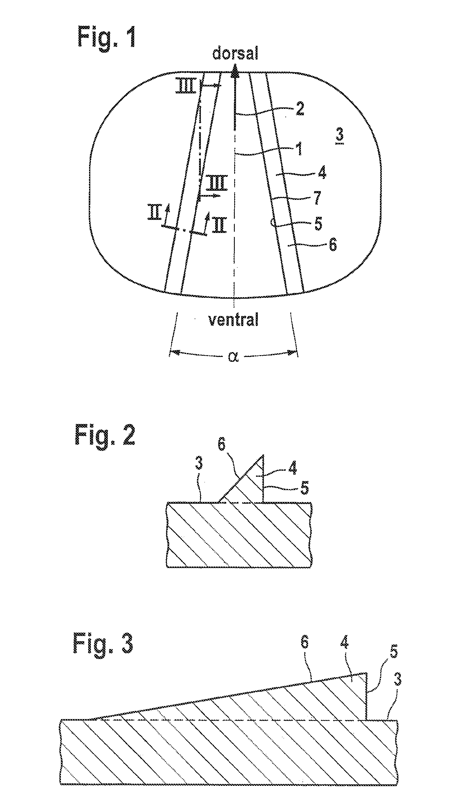
[0028]FIG. 1 shows the view of the attachment surface of an attachment plate of the prosthesis which is symmetrical with respect to the median plane 1. Its adaptation to the shape of the intervertebral space means that it has a predetermined ventral face and dorsal face. The implantation direction is also predetermined and, in the examples shown, is the direction 2 leading from ventral to dorsal.

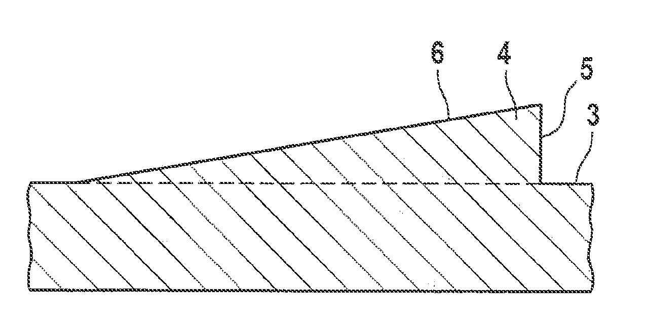
[0029]The attachment surface includes a base surface 3 which is intended to bear on the bone as far as possible across its entire surface area and can be provided with a surface structure permitting an intimate connection by means of bone tissue growing in pores or other recesses. The base surface surrounds two ribs 4 which are arranged symmetrically with respect to the median plane 1 and enclose an angle alpha of approximately 20°. Their more ventrally oriented side face 5 is steep, namely approximately 90° to the base surface 3, and the more dorsally oriented side face 6 running parallel t...


PUM


Abstract

An intervertebral prosthesis, in particular for the cervical spine, has two attachment plates connected in an articulated manner. The attachment surfaces of the attachment plates, which are configured for attachment to adjacent vertebral bodies have a base surface configured to bear on the surface of the vertebral bodies, and self-tapping fixing projections rising from the base surface. These fixing projections are formed by at least one pair of ribs which extend in opposite directions obliquely with respect to a predetermined implantation direction and whose side faces oriented more away from the implantation direction are steeper than their side faces oriented more in the implantation direction. The ribs can be toothed.

Description

REFERENCE TO RELATED APPLICATION[0001]This application is a continuation of U.S. application Ser. No. 11 / 472,543 filed Jun. 22, 2006, which claims the benefit under 35 U.S.C. §119(e) from U.S. provisional application Ser. No. 60 / 693,086, filed Jun. 23, 2005, the entire contents of which are hereby expressly incorporated by reference into this disclosure as if set forth fully therein.FIELD AND BACKGROUND OF THE INVENTION[0002]Intervertebral prostheses need to be fixed to the adjacent vertebral bodies in order to ensure that they do not shift from the position assigned to them. It is known to provide them with ribs or studs which are fitted into correspondingly shaped fixing recesses in the cover plates of the vertebral bodies (WO 01 / 01893, WO 2004 / 080355, DE-3023353, FR-A-2659226). Producing these requires deep working of the cover plates of the vertebral bodies, which entails considerable outlay in operating terms. Such working of the cover plates of the vertebral bodies is also und...

Claims


Application Information

Patent Timeline
Patent Type & Authority Applications(United States)
IPC IPC(8): A61F2/44
CPCA61F2002/30894A61F2002/30904A61F2230/0054A61F2/30771A61F2002/4445A61F2/4455A61F2002/30176A61F2002/30841A61F2002/30845A61F2/4425A61F2/44
Inventor KELLER, ARNOLD
Owner CERVITECH INC
Why Eureka
Try Eureka