
Self closing stationary umbrella

a stationary umbrella and self-closing technology, applied in the field of stationary umbrellas, can solve the problems of umbrella canopy and support system damage, damage to the fabric of the canopy, and damage to anything on which it may land

Inactive Publication Date: 2010-02-23
HATHAWAY MARTIN
View PDF17 Cites 58 Cited by
  • Summary
  • Abstract
  • Description
  • Claims
  • Application Information

AI Technical Summary

Benefits of technology

[0009]It is an object of the present invention to provide a mechanism for a self closing outdoor umbrella that causes the umbrella to close quickly and efficiently under windy conditions.
[0013]Another object of the present invention is to provide an umbrella assembly that is easy to manufacture and that performs well over time.
[0014]A still further object of the present invention is to provide an umbrella that will close quickly in windy conditions so that it cannot be lifted from its pedestal which can result in damage to the umbrella, to furniture and to the surroundings.
[0016]A further object of the present invention is to provide a mechanism that permits the umbrella to be manually closed by putting pressure on the support post.
[0017]A still further object of the present invention is to provide a ratcheted hand crank so that the crank will not spin when the umbrella is automatically lowered.
[0019]The present invention also teaches an outdoor umbrella that closes automatically when acted upon by high winds comprising a canopy, a canopy support including a fixed collar and pivotally attached primary ribs in cooperation with secondary ribs each secondary rib being pivotally attached at one end to a primary rib and at the other end to a slidable sleeve disposed beneath the collar, a pulley situated above the slidable sleeve, a rotatable horizontal shaft having a first end and a second end situated below the slidable sleeve, a flexible cable a first end of which is affixed to the horizontal shaft and the second end extending upward over the pulley and being affixed to the slidable sleeve, a crank assembly in cooperation with the second end of the horizontal shaft and a support base for supporting the umbrella on a horizontal surface. There is also a main tubular support post divided into two segments, an upper first segment in communication with a lower second segment, each segment having an upper end, a midpoint, and a lower end, the fixed collar being affixed to the upper end of the first segment, the slidable sleeve receiving the first segment and being slidable thereon, the pulley being mounted within said first segment between the collar and the slidable sleeve, an opening in a wall of the first segment adjacent to the pulley such that the second end of the flexible cable exits the first segment through the opening to reach said slidable sleeve and the horizontal shaft being rotatably mounted at substantially the midpoint of the first segment and extending outward through opposing walls thereof, the two segments enabling the assembly and maintenance of the contained structures. The umbrella further comprises means for exerting constant pressure on a secondary rib to close the canopy in response to the high winds and for preventing the canopy from reopening in the high winds, a releasable first ratchet assembly to support the first end of the horizontal shaft and restrict the rotation of the horizontal shaft until the umbrella is acted upon by the high winds, a second ratchet assembly to prevent the crank assembly from rotating as the horizontal shaft rotates when the umbrella is acted upon by the high winds, a trigger assembly to actuate the releasable first ratchet assembly, and means for automatically resetting the trigger assembly as the umbrella closes in response to the high winds.

Problems solved by technology

When an umbrella is left open and the weather changes abruptly, often there is no time to close the umbrella or the owner is not available to do so.
If there are high winds the umbrella canopy can sustain damage or the entire umbrella can be lifted from its anchor and travel some distance, causing damage to anything on which it may land.
Additionally, the umbrella canopy and support system can be severely damaged when the umbrella falls.
The spring causes the auxiliary post to resist but not prevent upward movement of the auxiliary post relative to the main post when wind acts on the canopy.
If there is wind, but not strong enough, the fabric of the canopy can be damaged and the umbrella will not close.

Method used


Image

  • Self closing stationary umbrella
  • Self closing stationary umbrella
  • Self closing stationary umbrella

Examples


Embodiment Construction

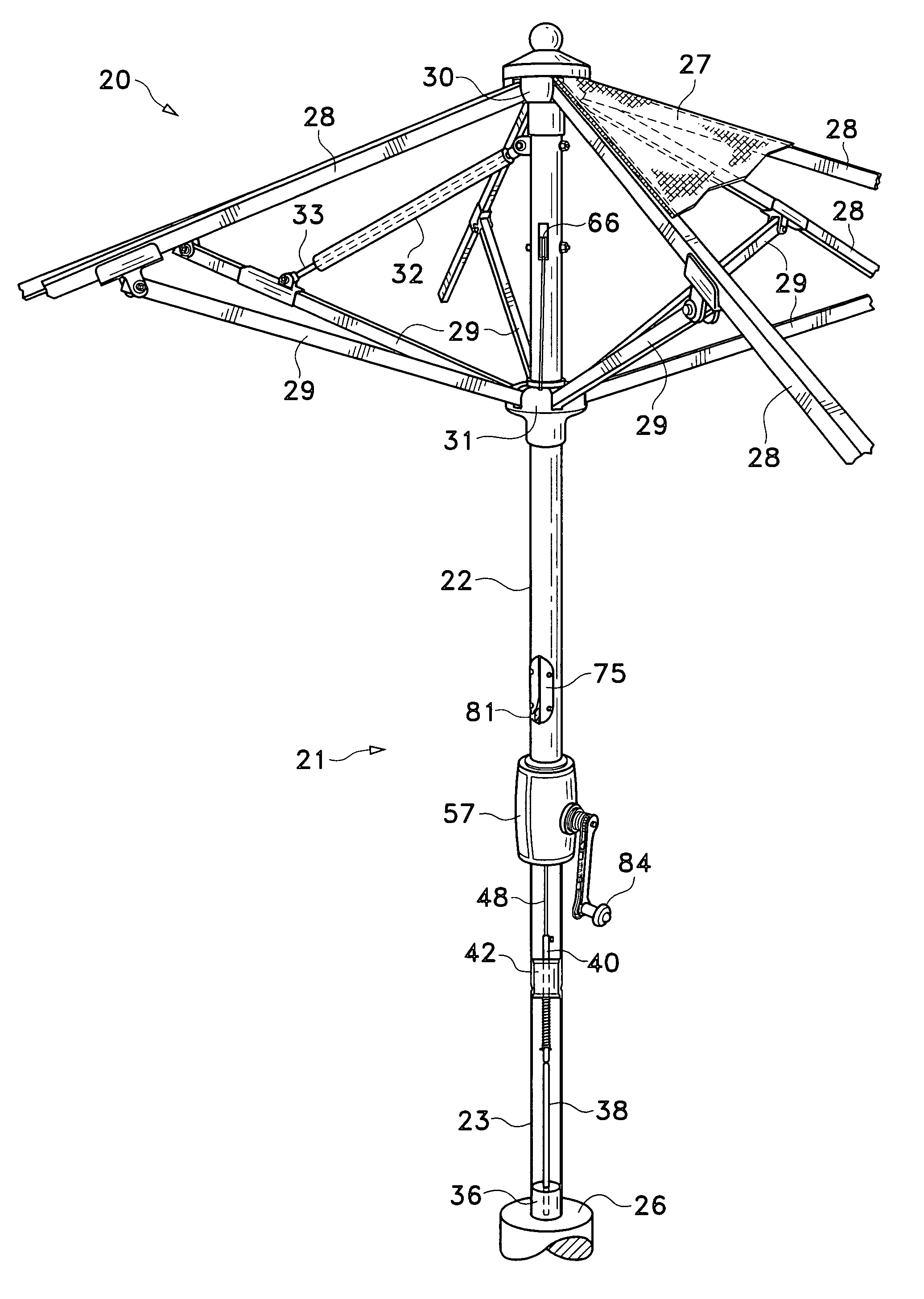
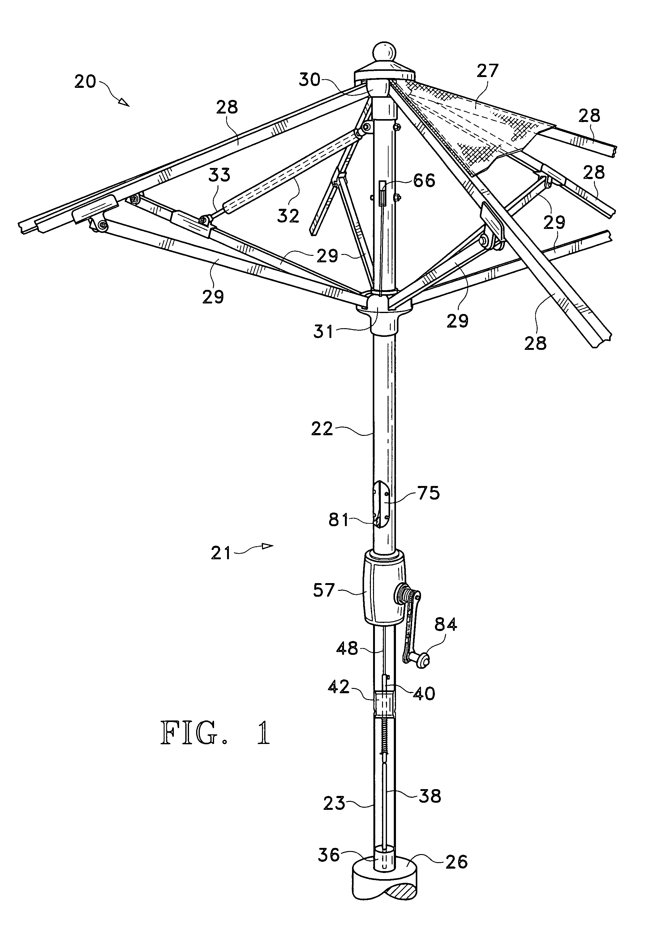
[0035]The umbrella 20 of the present invention may be represented inFIG. 1. From a first view of the umbrella 20 it may not appear to differ from those known in the prior art. Most of the mechanisms that control the present invention may be internal, i.e., located within the support system.

[0036]The umbrella 20 may be supported by a central support post 21 that is formed in two segments, an upper segment 22 and a lower segment 23. The bottom portion 24 of the upper segment 22 may be crimped to allow it to be close fitted into the top of the lower segment 22. The bottom of the lower segment 23 may be supported by any umbrella base 26 known in the art.

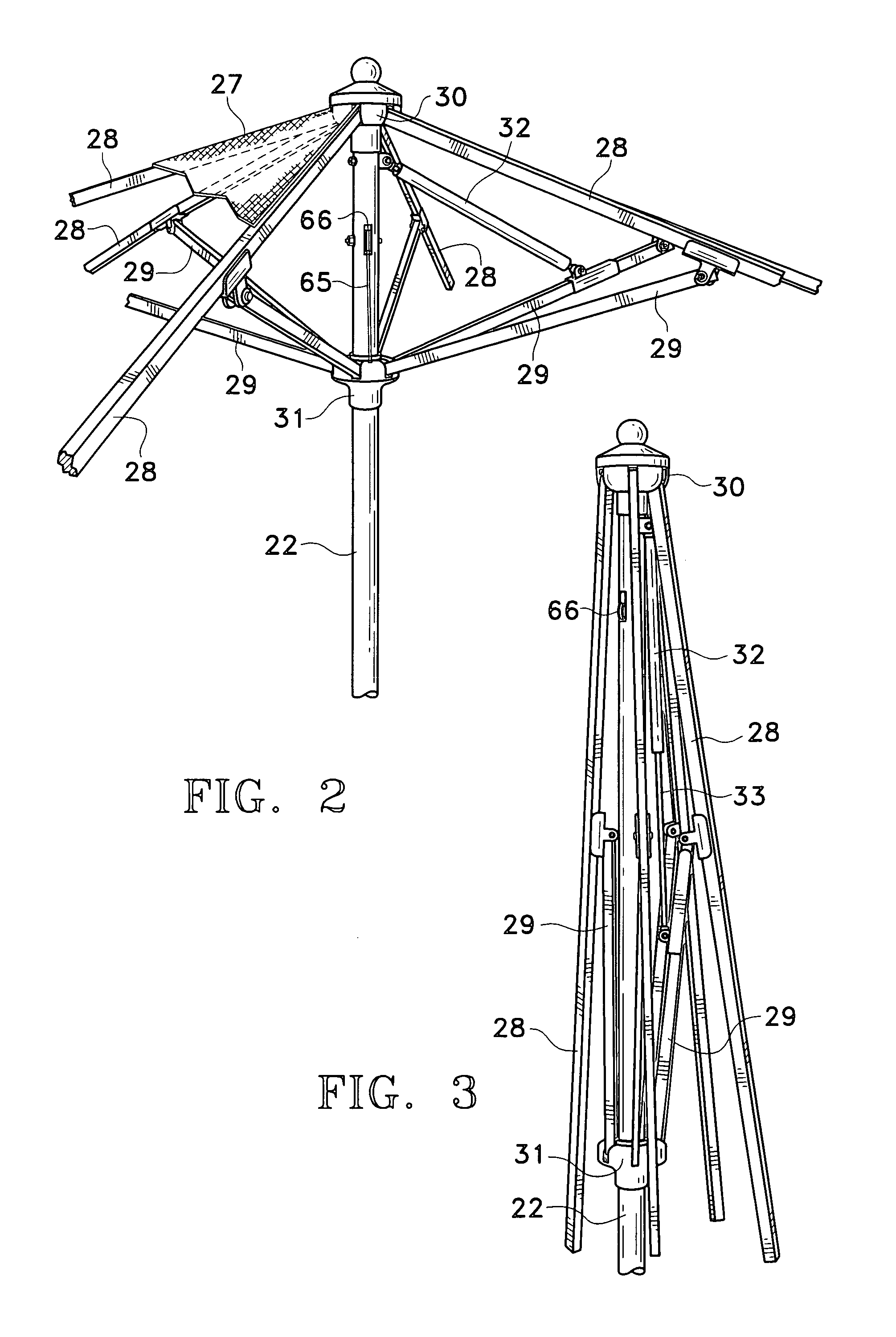
[0037]The canopy 27 of the umbrella 20 may be of any conventional material and may be supported by a plurality of primary ribs 28 and secondary ribs 29. The upper ends of the primary ribs 28 may be pivotally connected to a collar 30 affixed at the top of the upper segment 22 of the support post 21. The primary ribs 28 may extend outwardl...


PUM


Abstract

An outdoor umbrella that closes automatically in high wind is disclosed. The wind causes the main support post of the umbrella to flex from the vertical dislodging a plunger from its weight bearing mounting on a rigid rod. The plunger is attached to an actuator rod extending upward within the support post. When the plunger is displaced the actuator rod is caused to move downward thereby activating a releasing ratchet which frees a shaft to rotate and the cable which holds the canopy to unwind. A hydraulic cylinder attached to one of the canopy ribs presses on the rib to close the canopy and maintain the canopy in closed orientation. As the canopy closes a reset mechanism is activated which resets the plunger onto the rigid rod. Once closed the canopy will remain closed until raised by manually rewinding the cable onto the shaft using a hand crank attached to the end of the shaft. A second ratchet assembly incorporated into the hand crank prevents the hand crank from spinning when the umbrella closes.

Description

FIELD OF THE INVENTION[0001]The instant invention relates to a stationary outdoor umbrella that closes automatically when subject to high winds.BACKGROUND OF THE INVENTION[0002]Outdoor umbrellas have been in use for many years but they must be opened and closed manually. When an umbrella is left open and the weather changes abruptly, often there is no time to close the umbrella or the owner is not available to do so. If there are high winds the umbrella canopy can sustain damage or the entire umbrella can be lifted from its anchor and travel some distance, causing damage to anything on which it may land. Additionally, the umbrella canopy and support system can be severely damaged when the umbrella falls.[0003]There have been umbrellas developed to prevent wind damage when the umbrella is left open. Culver, in U.S. Pat. No. 6,330,886, discloses an outdoor umbrella with a canopy composed of a plurality of wedge shaped metal vanes or panels. The vanes are arranged such that one edge of...

Claims


Application Information

Patent Timeline
Patent Type & Authority Patents(United States)
IPC IPC(8): A45B25/14
CPCA45B25/006A45B25/143A45B25/22A45B2023/0012
Inventor HATHAWAY, MARTIN
Owner HATHAWAY MARTIN
Learn More