Surgical retractor
a retractor and surgical technology, applied in the field of surgical retractors, can solve the problems of deteriorating motor function of patients' extremities, affecting the performance of patients, and affecting the patient's extremities, so as to achieve the effect of improving performan
- Summary
- Abstract
- Description
- Claims
- Application Information
AI Technical Summary
Benefits of technology
Problems solved by technology
Method used
Image
Examples
first embodiment
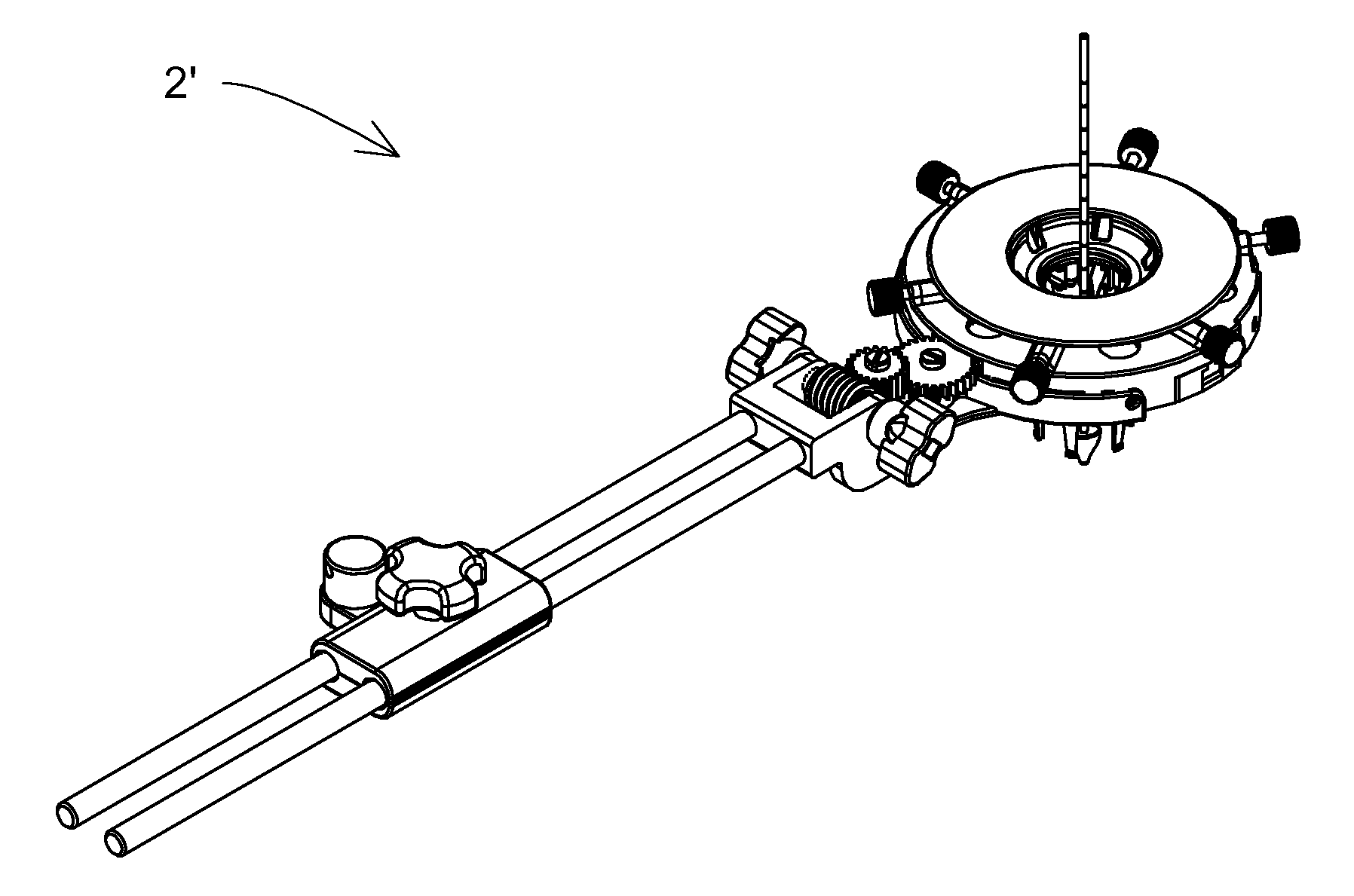
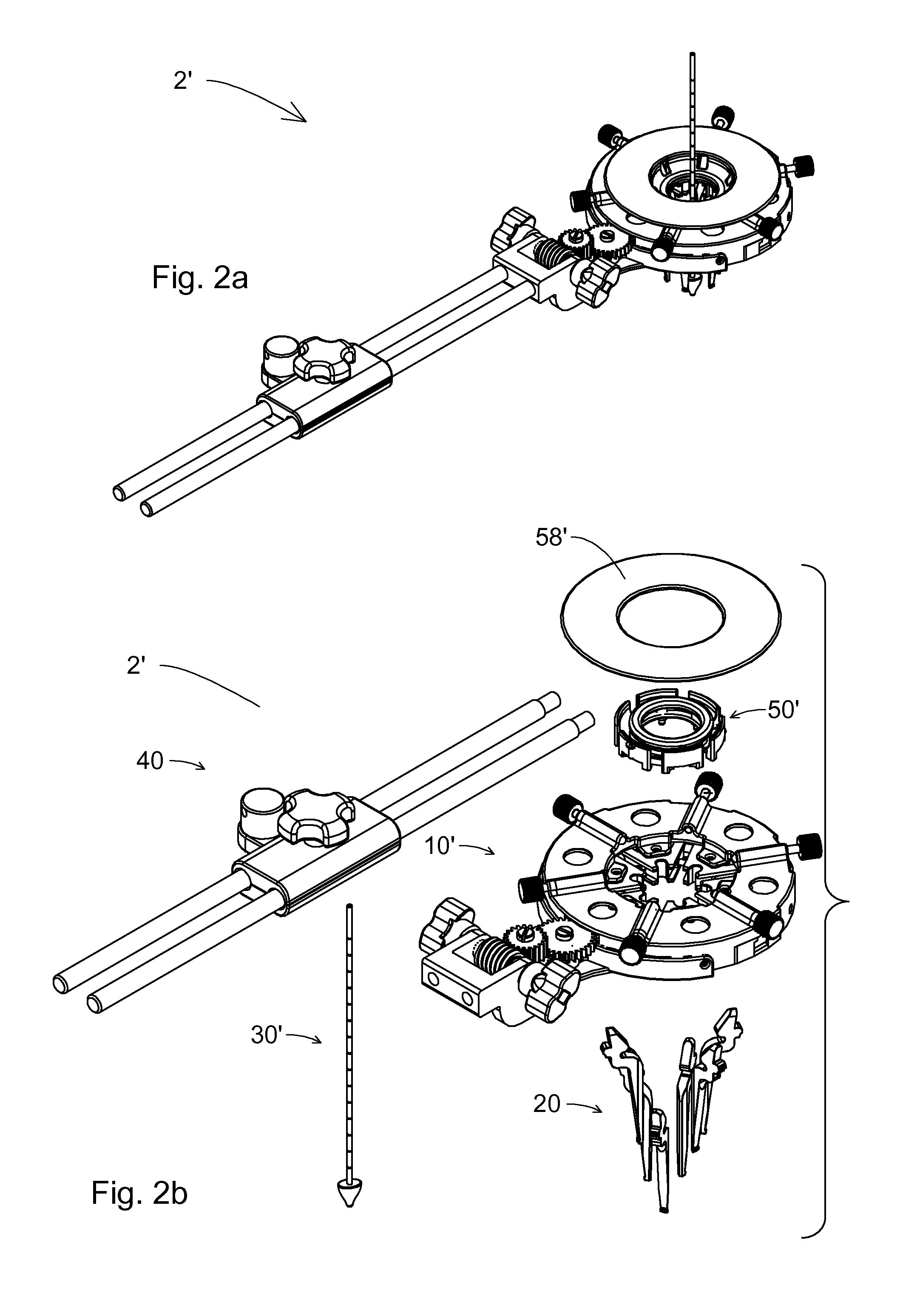
[0471]Referring now to the drawings, FIG. 2a, is an isometric side top view schematic illustration of a surgical retractor 2′ according to the present invention.
[0472]The surgical retractor 2′ is shown in an assembled state.
[0473]FIG. 2b, is exploded, isometric side top view schematic illustrations of a surgical retractor 2′, up to main assemblies, according to the first embodiment of the present invention.
[0474]The active assembly, which practically creates the opening in the operated patient's body for the purpose of performing the operation, is a ribs assembly 20, which can have an integrated central rod 30′, which leads the penetration into the body. The ribs assembly 20 has a wide range of opening states, which will be described in further detail in the following. These opening states are commanded and controlled by a mechanism for transferring of linear and rotational movements 10′. In addition, the surgical retractor 2′, according to the present invention, can include a light...
second embodiment
[0718]FIG. 29a is an isometric front top view schematic illustration of a surgical retractor 2″ according to the present invention.
[0719]This embodiment is simpler than the first embodiment. It includes less part, can be more lightweight, and can likewise be less expensive. As such, it can be suitable for single-time use, as a whole or the majority of its parts.
[0720]This embodiment includes the same ribs 21, for all features, as described so far according to the present invention. The ribs 21 of all the embodiments can be made of material or materials transparent to x-rays.
[0721]The channeled disc 13″ and the slider 15″ of the surgical retractor 2″ according to second embodiment differ in shape from the channeled disc 13″ and the slider 15″ of the surgical retractor 2′ according to first embodiment. However, in both embodiments, the sliders 15′, 15″ are assembled into channeled discs 13′, 13″ so as to enable linear radial movement relative to the centers channeled discs 13′, 13″.
[0...
third embodiment
[0798]FIG. 45a is a front view schematic illustration of a surgical retractor 2′″ according to the present invention.
[0799]The third embodiment includes, as will be further shown, mechanisms for generation of radial, linear, and angular movement of the ribs 21, similar to the mechanisms of the surgical retractor 2′ according to the first embodiment of the present invention, however the transmission 17′″ of the third embodiment is much simpler. Likewise, an auxiliary handle 59a is added to facilitate the insertion of the ribs 21 into the body of the operated patient.
[0800]The auxiliary handle 59a can be composed of metal and is removed from the surgical retractor 2′″ after insertion is completed.
[0801]FIG. 45b is an isometric top view schematic illustration of a surgical retractor 2′″ according to a third embodiment of the present invention.
[0802]The present illustration shows a wrench 59b (such as ratchet wrench) mounted on the surgical retractor 2′″. The wrench 59b serves for trans...
PUM
 Abstract
Description
Claims
Application Information
 - R&D
- Intellectual Property
- Life Sciences
- Materials
- Tech Scout
- Unparalleled Data Quality
- Higher Quality Content
- 60% Fewer Hallucinations
Browse by: Latest US Patents, China's latest patents, Technical Efficacy Thesaurus, Application Domain, Technology Topic, Popular Technical Reports.
© 2025 PatSnap. All rights reserved.Legal|Privacy policy|Modern Slavery Act Transparency Statement|Sitemap|About US| Contact US: help@patsnap.com


