Apparatus and method for monitoring the output of a warning or indicator light

a technology of warning or indicator light and apparatus, which is applied in the direction of traffic control supervision, optical radiation measurement, instruments, etc., can solve the problems of sensor output accuracy and sensor exposur

Active Publication Date: 2006-10-17
GENERAL ELECTRIC CO
View PDF12 Cites 25 Cited by
  • Summary
  • Abstract
  • Description
  • Claims
  • Application Information

AI Technical Summary

Benefits of technology

[0009]The lens forms an image of the entire roundel face so that the intensity distribution corresponding to what the detector sees can be attenuated or transmitted at each point of the roundel to create a uniform response.

Problems solved by technology

Such equipment must necessarily be located throughout the railroad system, and is thus geographically dispersed and often located at places that are difficult to access.
However, the location of the sensor or photo sensor may cause the sensor to be exposed to environmental conditions that may affect the accurancy of the sensor output.
Furthermore, and in order to not block the light output while also measuring the same, the sensor may be positioned such that it will detect a non-uniform light signal (e.g., the sensor is not centrally located with respect to the light).

Method used


Image

  • Apparatus and method for monitoring the output of a warning or indicator light
  • Apparatus and method for monitoring the output of a warning or indicator light
  • Apparatus and method for monitoring the output of a warning or indicator light

Examples


Embodiment Construction

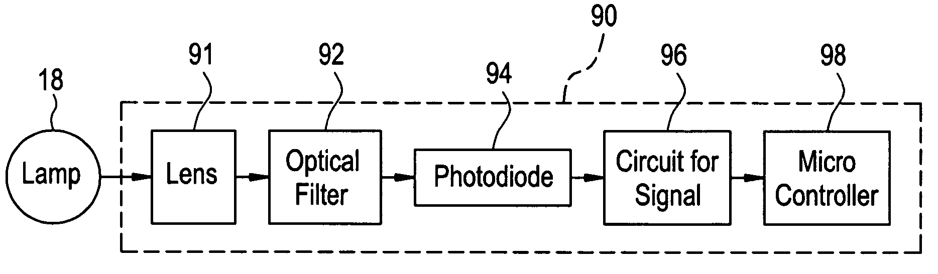
[0027]Disclosed herein is an operational status detection system for a railroad warning device having a warning light. The system will remotely provide a signal indicative of the operational status of the warning light. The system includes a photodiode or other optical sensor configured to generate a signal corresponding to light output of the warning light of the railroad warning device when the device is activated. The signal is filtered to provide a uniform response corresponding to the light output of the warning light. More specifically, and in accordance with exemplary embodiments, the photodiode is provided with an optical filter, which in conjunction with a lens filters the radiated light of the warning light to provide a spatially uniform light output (relative to the warning light face) to the photodiode. In other words, the optical filter adjusts or filters the light signal so that a uniform light output is provided to the photodiode, wherein stronger portions of the ligh...


PUM


Abstract

An operational status detection system for a railroad warning device having a warning light, comprising: a photo detector configured to generate a signal corresponding to a light output of the warning light of the railroad warning device, the photo detector comprising a lens, an optical filter and a photodiode, wherein the optical filter is disposed between the photodiode and the lens and the optical filter is configured to provide the light output of the warning light to be presented as a substantially uniform spatial response to the photodiode wherein areas of high intensity of the warning light that are received by the lens are attenuated, the areas of high intensity providing higher light outputs than other areas of the warning light; and a microcontroller for receiving the signal, wherein the microcontroller compares the signal to at least one threshold value, the at least one threshold value corresponding to an acceptable light output of the warning light.

Description

BACKGROUND[0001]This invention relates generally to railroad crossing and wayside signals, and more particularly a method and apparatus for monitoring the operational status of the railroad crossing signal.[0002]Railroad systems include wayside equipment such as switches, signals, and vehicle detectors including hot wheel detectors, dragging equipment detectors, high / wide load detectors, vehicle identification systems, etc. Such equipment must necessarily be located throughout the railroad system, and is thus geographically dispersed and often located at places that are difficult to access. Systems are currently in use for communicating operational and status information relating to the condition of the train or the track to control centers through various types of modems. For example, position indicators are provided on switches and a signal responsive to the position of a switch is communicated to a control center for that section of track.[0003]Grade crossings where streets and r...

Claims


Application Information

Patent Timeline
Patent Type & Authority Patents(United States)
IPC IPC(8): G08G1/097
CPCB61L5/1881B61L29/30G01J1/42G08B5/36G01J1/0271G01J1/0488
Inventor DAVENPORT, DAVID MICHAELMEYERS, MARK MARSHALL
Owner GENERAL ELECTRIC CO
Why Eureka
Try Eureka