Watch including a pressure sensor

a pressure sensor and watch technology, applied in the field of watches, can solve the problems of difficult operation and more complicated construction of the components, and achieve the effects of precise positioning of the printed circuit element, and convenient assembly of the sensor modul

Active Publication Date: 2006-10-17
ETA SA MFG HORLOGERE SUISSE
View PDF11 Cites 15 Cited by
  • Summary
  • Abstract
  • Description
  • Claims
  • Application Information

AI Technical Summary

Benefits of technology

[0005]It is an object of the present invention to overcome the drawbacks of the prior art owing to a device for mounting the pressure sensor in the back cover of the watchcase that provides a very high level of precision in positioning the various elements, in particular for guaranteeing the mutual positioning of the electrical contacts before applying them against each other, with a simple and easy method of assembling the parts of the device, then the watch itself. Moreover, the mounting device should allow use of a standard type of pressure sensor, easily available on the market.
[0007]Thus, the intermediate ring ensures very precise positioning of the printed circuit element relative to the sensor, enabling electrical connections to be used simply by contact and without any welding between the contact pads of the element and the sensor terminals, which facilitates the assembly of the sensor module. Further, this ring ensures very precise positioning of the printed circuit element and the sensor module assembly relative to the back cover of the case, and thus relative to the rest of the case and to the main printed circuit board, to which the module has to be electrically connected, for example by means of connection elements such as springs housed in the sensor support. Precise centring of the sensor module in the back cover orifice can be achieved either on the intermediate ring in the orifice, or on the tubular casing of the sensor, which is itself driven into said ring. These arrangements also facilitate the assembly of the watch, by establishing electrical contacts between the sensor module and the other circuits in an extremely simple manner, particular by avoiding the use of a flexible printed circuit. The fact that the output members of the sensor module are positioned as directly as possible in relation to the watchcase breaks the usual chain of tolerances that accumulate in conventional mounting devices.
[0008]In a preferred embodiment of the invention, the tubular casing of the sensor is prominent relative to a frontal face of the intermediate ring, in the direction of the external side of the back cover, and an annular sealing gasket makes the mounting of the sensor module in the back cover water-resistant, for example an O-ring joint, which is radially compressed between said tubular casing and a wall of the back cover orifice, said annular sealing gasket being capable of abutting axially against the frontal face of the intermediate ring. In other words, this ring is located behind the annular sealing gasket, such that the external pressure and humidity cannot reach the contact surfaces between the back cover and the intermediate ring, or those between the intermediate ring and the sensor. Moreover, the sealing gasket is small and the operation of assembling the sensor module with the back cover is easy, as will be explained hereinafter.

Problems solved by technology

However, if one wishes to associate the sensor with a printed circuit element that directly processes these output signals, in particular to calibrate pressure measurements by calibrating parameters that are individually determined for each sensor, the construction is more complicated and problems arise in the precise mutual positioning of the electric contacts.
But if this flexible element has to connect the sensor to an additional printed circuit board to process the sensor signals, multiple, successive, sometimes difficult operations are required to mount these components respectively on the back cover and in the case.

Method used


Image

  • Watch including a pressure sensor
  • Watch including a pressure sensor
  • Watch including a pressure sensor

Examples


Embodiment Construction

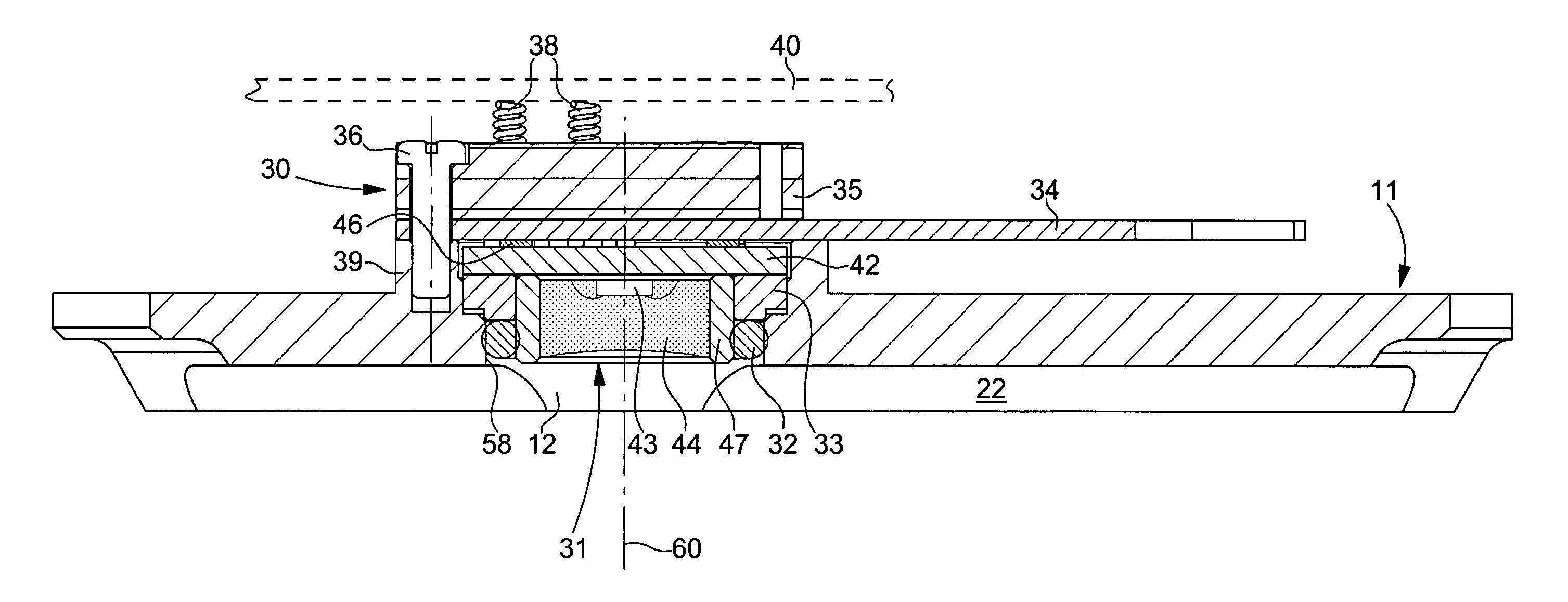
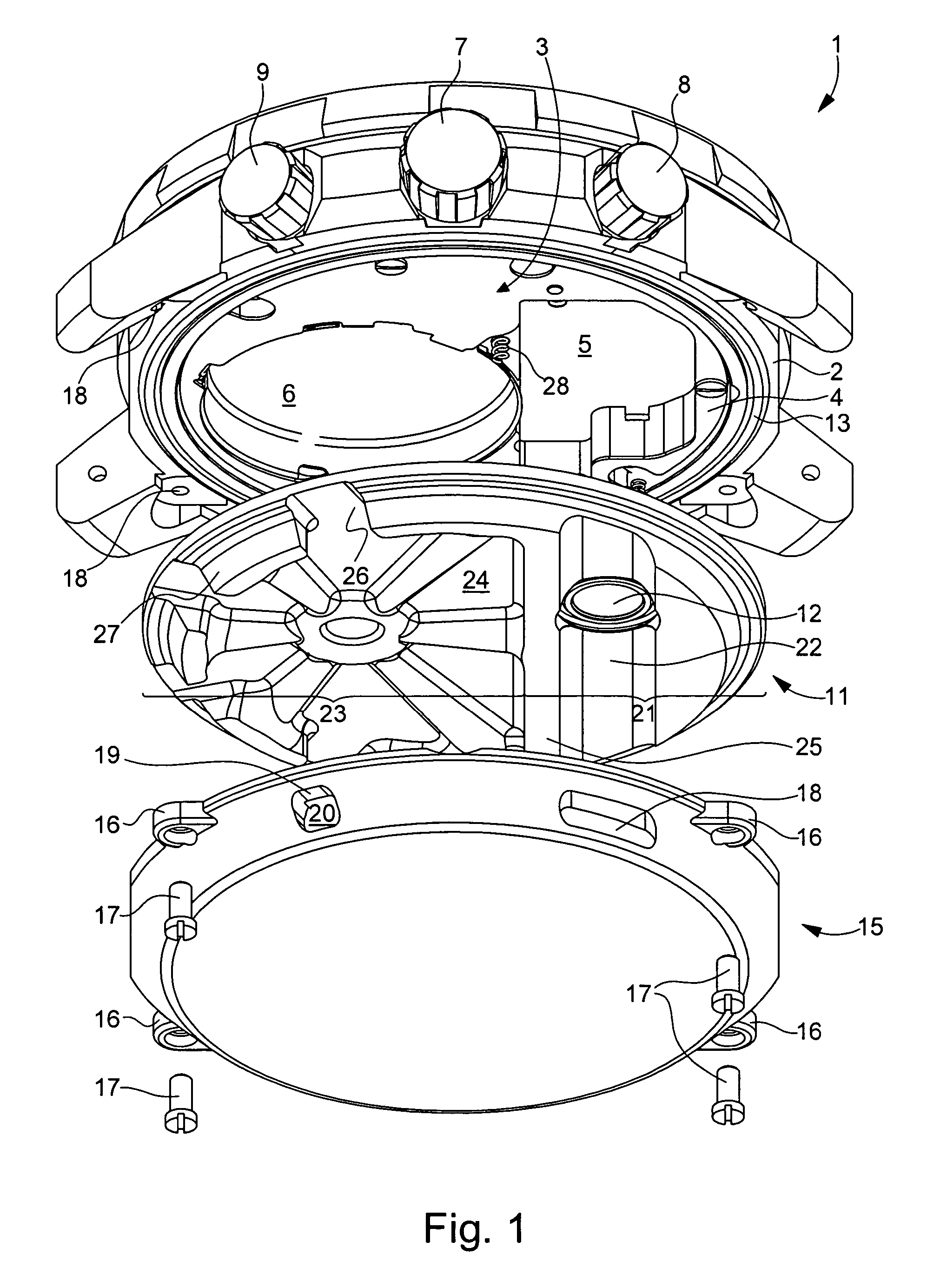
[0014]The diver's wristwatch 1 shown in an exploded view in FIG. 1 comprises, in a conventional manner, a case whose middle part 2 surrounds the electronic watch movement 3, which is supported by a plate 4 made of an insulating material. FIG. 1 shows that plate 4 includes in particular a housing 5 for a sensor module 30 (FIG. 2) and a housing 6 for an electric battery powering the watch. The sensor module includes a pressure sensor which, in a known manner, supplies output signals which represent in particular the ambient pressure and which are processed by the electronic movement to provide a pressure indication via the watch display means, whose functions are controlled by the user by means of a crown 7 and push-buttons 8 and 9.

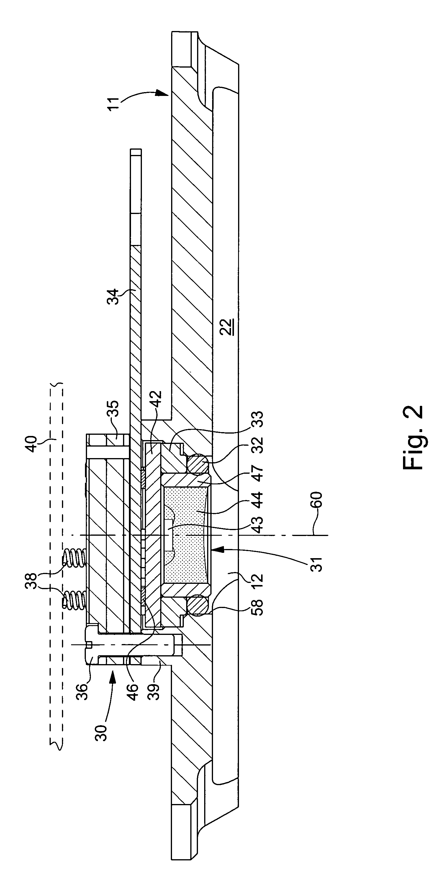
[0015]The pressure sensor module is mounted in an orifice 12 of a back cover 11 which closes the bottom of the watchcase in a water-resistant manner, by being pressed against an annular sealing gasket 13 housed in a groove of middle part 2. In the present c...


PUM


Abstract

The invention concerns a device for mounting a pressure sensor simply and precisely on the back cover (11) of a diver's watch or altimeter watch. The pressure sensor (31) is driven into an intermediate ring (33) forming part of a sensor module (30) which further includes an additional PCB (34), a sensor support (35) and connecting elements (38) between the additional PCB (34) and a main PCB of the watch. To ensure very precise positioning relative to the back cover, the intermediate ring (33) includes feet (35) that engage in holes in the additional PCB and in the sensor support. A sealing gasket (32) is radially compressed between the wall of the orifice (12) of the back cover and a tubular casing (47) of the pressure sensor. The back cover (11) is covered externally by a perforated cover.

Description

[0001]This application claims priority from European Patent Application No. 04029987.7, filed Dec. 17, 2004, the entire disclosure of which is incorporated herein by reference.BACKGROUND OF THE INVENTION[0002]The present invention concerns a watch of the type comprising a case provided with a back cover that is resistant to ambient pressure, a pressure sensor mounted in an orifice of the back cover with an intermediate ring, and a printed circuit element connected to terminals of the pressure sensor, said sensor comprising a rigid substrate fitted with said terminals, a tubular casing secured to the substrate in a water-resistant manner and arranged to fit into the intermediate ring, and a pressure sensitive element, which is mounted on the substrate and located inside the tubular casing.[0003]In some watches having a pressure sensor mounted on the water-resistant back cover of the watchcase, vertical helical springs are provided for electrically connecting the terminals of the sens...

Claims


Application Information

Patent Timeline
Patent Type & Authority Patents(United States)
IPC IPC(8): G04B47/06G04B37/00G04G99/00
CPCG04G21/02B63C11/02G04B37/04G04B37/00G04B47/06
Inventor ROBERT, PASCALMARTI, FELIX
Owner ETA SA MFG HORLOGERE SUISSE
Why Eureka
Try Eureka