Recording apparatus and recording method

a recording apparatus and recording method technology, applied in the field of recording apparatus and recording method, can solve the problems of increasing recording data jitter and recording data cannot be read, and achieve the effect of improving the quality of recording data and reducing thermal interference between codes (pits and lands) to be recorded

Inactive Publication Date: 2006-10-17
SONY CORP
View PDF8 Cites 3 Cited by
  • Summary
  • Abstract
  • Description
  • Claims
  • Application Information

AI Technical Summary

Benefits of technology

[0023]Accordingly, it is an object of the present invention to implement laser power control so that appropriate recording is performed at a fast recording rate.
[0035]Accordingly, thermal interference between codes (pits and lands) to be recorded is reduced. When recording at a fast recording rate, such as a ×8 speed, appropriate pits and lands are formed in which a sufficient read margin is obtained. A reduction in recording jitter improves the quality of recording data. Recording in accordance with a recording environment is performed.

Problems solved by technology

Upon recording at the ×8 speed, when the laser power is controlled by the method shown in FIG. 14 or by the method shown in FIG. 15, intersymbol interference occurs, and jitter of the recording data increases.
In the worst case, the recording data cannot be read.

Method used


Image

  • Recording apparatus and recording method
  • Recording apparatus and recording method
  • Recording apparatus and recording method

Examples


Embodiment Construction

[0054]The present invention will be understood from the following description of a disk drive according to an embodiment which conforms to CD-R and CD-RW.

[0055]CD-R is a write-once medium in which organic dye is used to form a recording layer. CD-RW is a medium in which data can be rewritten by using a phase change technique.

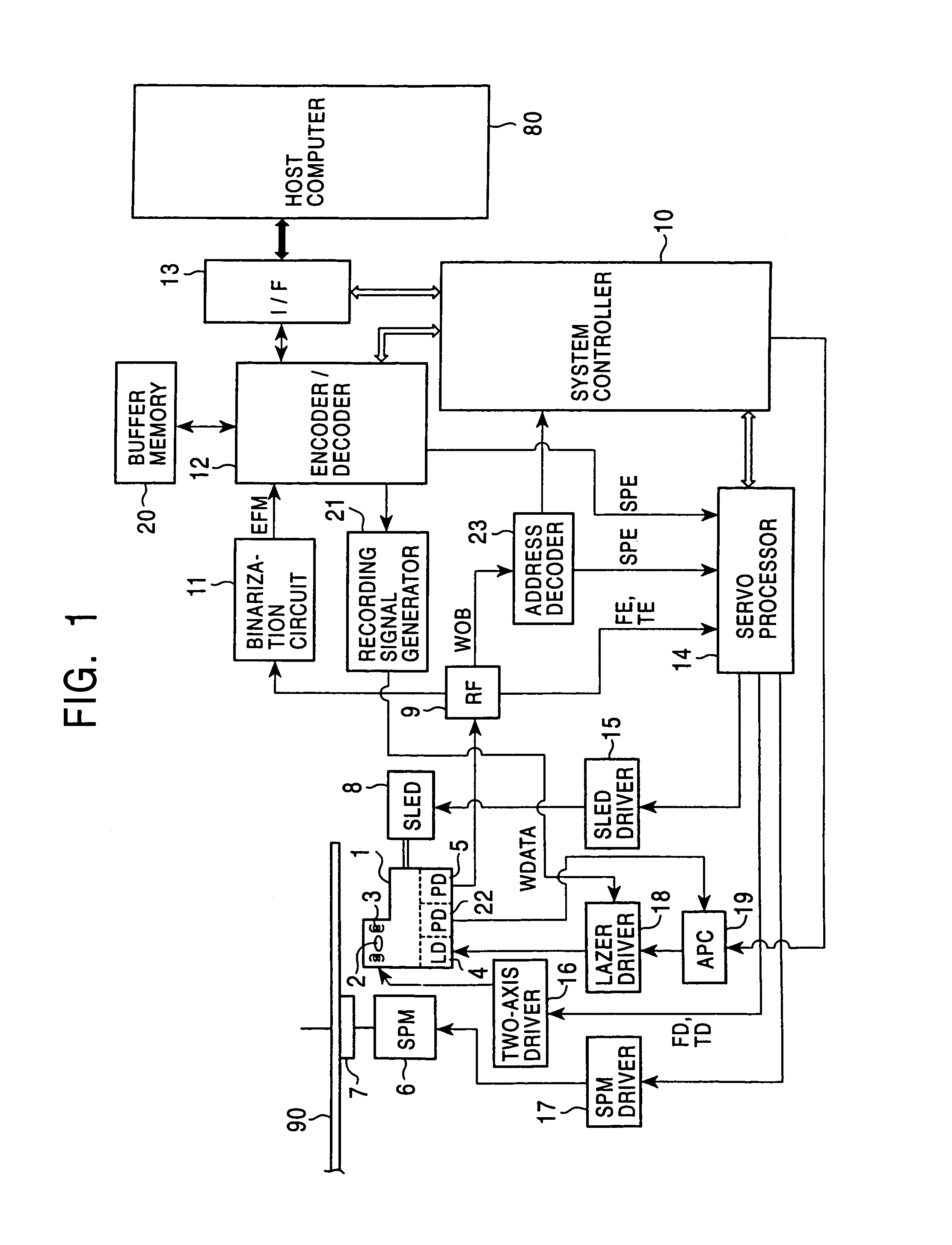
[0056]Referring to FIG. 1, the structure of the disk drive according to the embodiment for reading and writing data to a disk such as a CD-R or a CD-RW disk is described.

[0057]In FIG. 1, a disk 90 is a CD-R or a CD-RW disk. Also, a CD-DA or a CD-ROM as the disk 90 can be read.

[0058]The disk 90 is mounted on a turntable 7. When reading or writing, the turntable 7 is rotated and driven by a spindle motor 1 at a constant linear velocity (CLV) or a constant angular velocity (CAV). An optical pick-up 1 reads pit date (phase change pits or pits formed by organic dye change (reflectivity change)) on the disk 90. In the case of the CD-DA or the CD-ROM, the pits are embo...


PUM

PropertyMeasurementUnit
speedaaaaaaaaaa
recording power levelaaaaaaaaaa
widthaaaaaaaaaa

Abstract

A recording apparatus generates a first pulse (EQEFM signal) in accordance with recording data such as an EFM signal. A second pulse (first overdrive pulse) to be combined with substantially the leading edge of the first pulse is generated. A third pulse (end overdrive pulse) to be combined with substantially the trailing edge of the first pulse is generated. The first, second, and third pulses are combined to synthesize a driving pulse, and the driving pulse is supplied to a laser unit. At least one of the first, second, and third pulses is controlled so that one of the level and the pulse duration thereof is varied in accordance with the length of formed pits and lands.

Description

CROSS-REFERENCE TO RELATED APPLICATIONS[0001]The present application is a divisional of application Ser. No. 10 / 615,917, filed Jul. 10, 2003 now U.S. Pat. No. 6,856,588, which is a divisional of application Ser. No. 09 / 650,929, filed Aug. 29, 2000 (now U.S. Pat. No. 6,614,739), which in turn claims priority from Japanese Application No. P11-244930, filed Aug. 31, 1999.BACKGROUND OF THE INVENTION[0002]1. Field of the Invention[0003]The present invention relates to a recording apparatus and a recording method for performing light modulation recording, that is, data recording on a recording medium by a laser beam modulated by recording data.[0004]2. Description of the Related Art[0005]When performing light modulation recording on a recording medium such as an optical disk or the like, a laser emits light in pulses in order to perform thermal control for shaping a pit (mark) to be formed on the disk.[0006]Specifically, a pulse waveform as a driving pulse for driving the laser is arrange...

Claims


Application Information

Patent Timeline
Patent Type & Authority Patents(United States)
IPC IPC(8): G11B7/00G11B7/0045
CPCG11B7/00456
Inventor SASAKI, TAKASHIMORIICHI, MUNETOSHIBAMBA, MITSUYUKIMASUDA, YOSHIYASU
Owner SONY CORP
Why Eureka
Try Eureka