Eureka AIR delivers breakthrough ideas for toughest innovation challenges, trusted by R&D personnel around the world.

Apparatus and method for scaling TCP off load buffer requirements by segment size

Inactive Publication Date: 2006-10-17
MICROSOFT TECH LICENSING LLC
View PDF16 Cites 62 Cited by
  • Summary
  • Abstract
  • Description
  • Claims
  • Application Information

AI Technical Summary

Benefits of technology

[0009]The present invention provides a method to ensure that there is enough information in each transport segment to allow the data being sent in the transport segment to be placed in the client's buffer. A framing header is aligned with the transport segment header so that the framing header is at the beginning of the transport segment. Information is placed in the framing header that describes the transport segment in sufficient detail to allow the data in the transport segment to be placed in its final destination. This effectively eliminates the need for an intermediate reassembly buffer in the performance path (i.e., the primary path in which the data is being received).

Problems solved by technology

One of the problems that has occurred as a result of the increased data flow is segment delay, segment loss and reordering of segments (e.g., segments arriving out of order).
The segment delay, segment loss, and reordering of segments causes problems for many applications that rely on the data being received timely and in the order it was sent.
The required buffer memory is a problem when the Transmission Control Protocol (TCP) is offloaded from the host to a network interface card (NIC).
Today, network interface cards having megabytes or gigabytes of memory are not cost competitive due to the memory size and high speed requirements.
However, the ULP PDU is not always identical to the size of the transport segment used by the transport protocol to send the data over the network.
The transport segments that do not contain the ULP PDU header are called non self-describing transport segments because they do not have sufficient information to directly place the data into its final location.
If the period is high relative to packet loss rate (e.g., once per segment), the location of the next PDU can be found with a very high likelihood when a previous PDU header has been lost.
The problem with this solution is that data must still be buffered.

Method used


Image

  • Apparatus and method for scaling TCP off load buffer requirements by segment size
  • Apparatus and method for scaling TCP off load buffer requirements by segment size
  • Apparatus and method for scaling TCP off load buffer requirements by segment size

Examples


Embodiment Construction

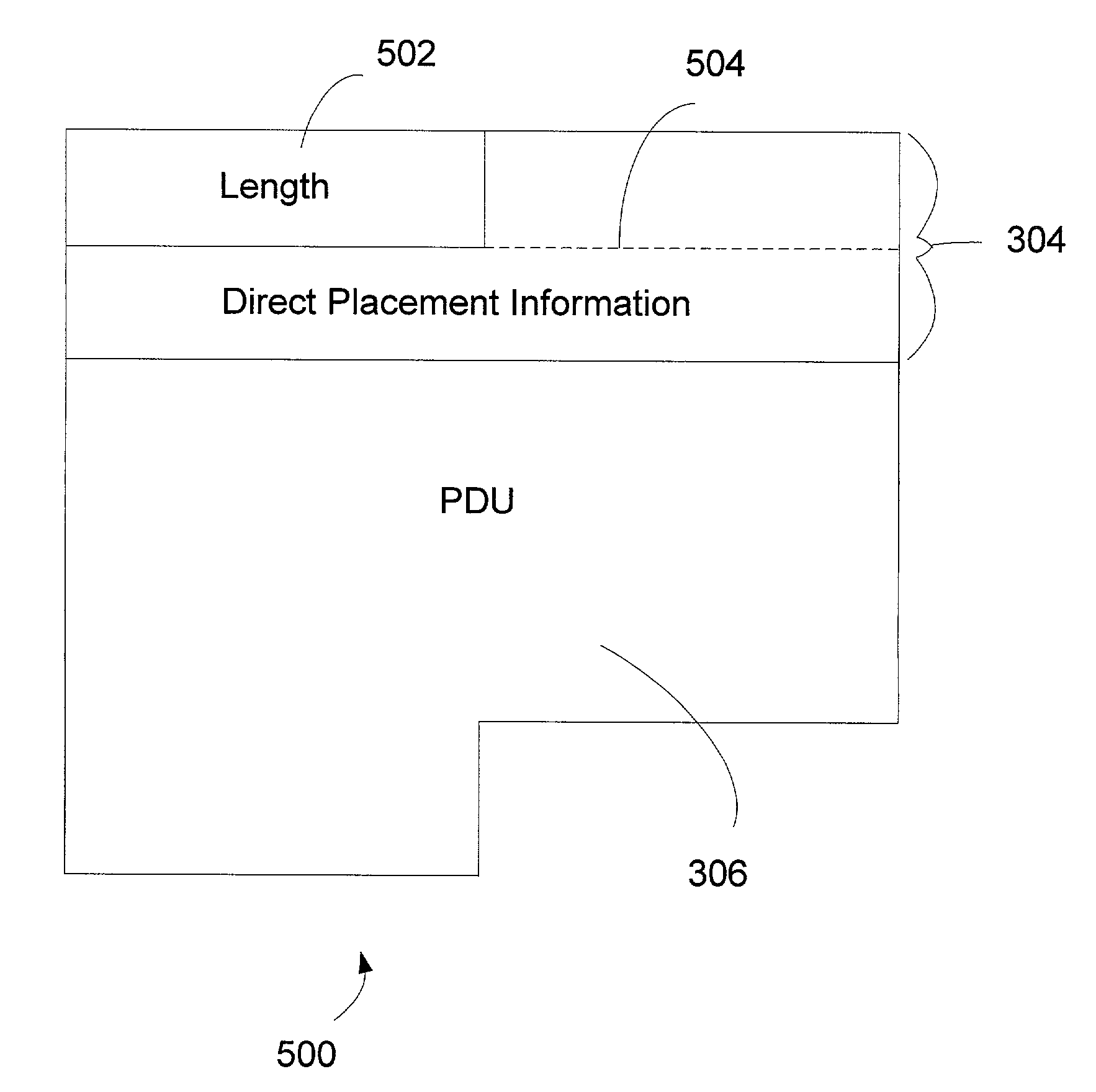
[0020]The present invention ensures that ULP PDUs received out of order do not have to be buffered by an intermediate reassembly buffer in the performance path. To provide this ensurance, each transport segment begins with segment description information and contains an integral number of ULP PDUs. Segment description information is information that is sufficient for direct data placement to occur. Direct data placement occurs when a receiving node directly maps the incoming data (e.g., the data in the ULP PDU) to a specific ULP buffer and a specific offset within that buffer. In this way, the destination location of the ULP PDU is known and the out of order ULP PDU is placed in its destination location. The size of the buffer memory required is reduced to:

k*(the maximum transport segment size)

where k is a constant. In systems having direct placement capability, the present invention allows the data in each transport segment to be placed in its final destination independently of all...


PUM


Abstract

A method and apparatus to ensure that protocol data units received out of order do not have to be buffered by a reassembly buffer in the performance path is presented. When an application or device requests to transfer data with another application or device, a framing protocol sends one or more complete protocol data units preceded by a framing header that is aligned with the transport header. The framing header contains information that allows the receiving application or device to determine where the protocol data unit should be placed so that successive protocol data units can be recovered when a previous protocol data unit has been received out of order.

Description

FIELD OF THE INVENTION[0001]This invention relates generally to networked communications and, more particularly, relates to a system and method for managing the buffering of data in systems having transport layers that do not have self-describing transport segments.BACKGROUND OF THE INVENTION[0002]Computer networking allows applications residing on separate computers or devices to communicate with each other by passing data across the network connecting the computers. The amount of data segments being sent across networks is rapidly increasing. The increase is due to several factors. These factors include the growth in the number of networked computers and the explosion in growth of digitally based multimedia, which is the combination of video and audio in a digital format for viewing on a computer or other digital device.[0003]Data is typically sent in segments or packets. One of the problems that has occurred as a result of the increased data flow is segment delay, segment loss an...

Claims


Application Information

Patent Timeline
IPC IPC(8): G06F15/16H04L29/06H04L29/08
CPCH04L29/06H04L67/2804H04L67/10H04L69/22H04L69/06H04L67/561H04L9/40
Inventor PINKERTON, JIM
Owner MICROSOFT TECH LICENSING LLC
Why Eureka
Eureka Blog
Learn More