Eureka AIR delivers breakthrough ideas for toughest innovation challenges, trusted by R&D personnel around the world.

Data storage system having cache memory manager with packet switching network

a data storage system and cache memory technology, applied in the field of data storage systems, can solve the problem of increasing the data transfer bandwidth of the system, and achieve the effect of increasing the operating bandwidth of the system interfa

Inactive Publication Date: 2006-10-17
EMC IP HLDG CO LLC
View PDF12 Cites 15 Cited by
  • Summary
  • Abstract
  • Description
  • Claims
  • Application Information

AI Technical Summary

Benefits of technology

The present invention provides a system interface with a cache memory and a cache memory manager. The cache memory manager is connected to the front end and back end directors, which control data transfer between the host computer / server and the bank of disk drives. The cache memory manager has a memory that stores a map of data stored in the cache memory and the disk drives. The cache memory manager determines whether data to be read from the disk drives or written to the disk drives is in the cache memory. The cache memory manager is connected to a messaging network that operates independently of the data transfer section. This arrangement increases the operating bandwidth of the system interface and reduces the burden on the cache memory.

Problems solved by technology

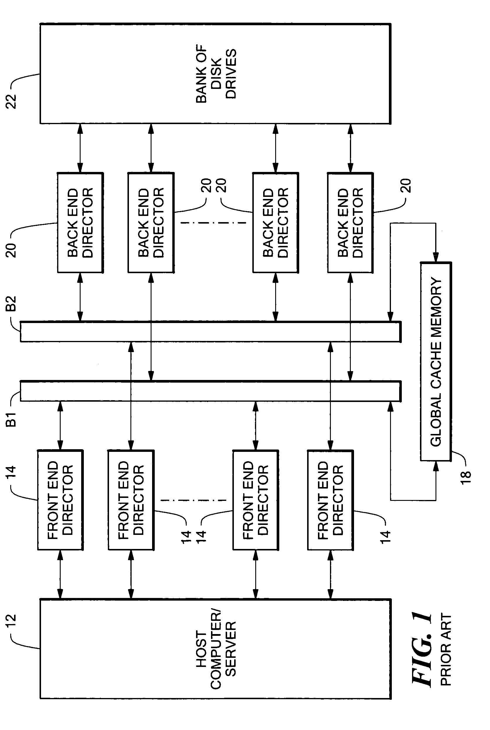
Further, the use of two buses increases the data transfer bandwidth of the system compared to a system having a single bus.

Method used


Image

  • Data storage system having cache memory manager with packet switching network
  • Data storage system having cache memory manager with packet switching network
  • Data storage system having cache memory manager with packet switching network

Examples


Embodiment Construction

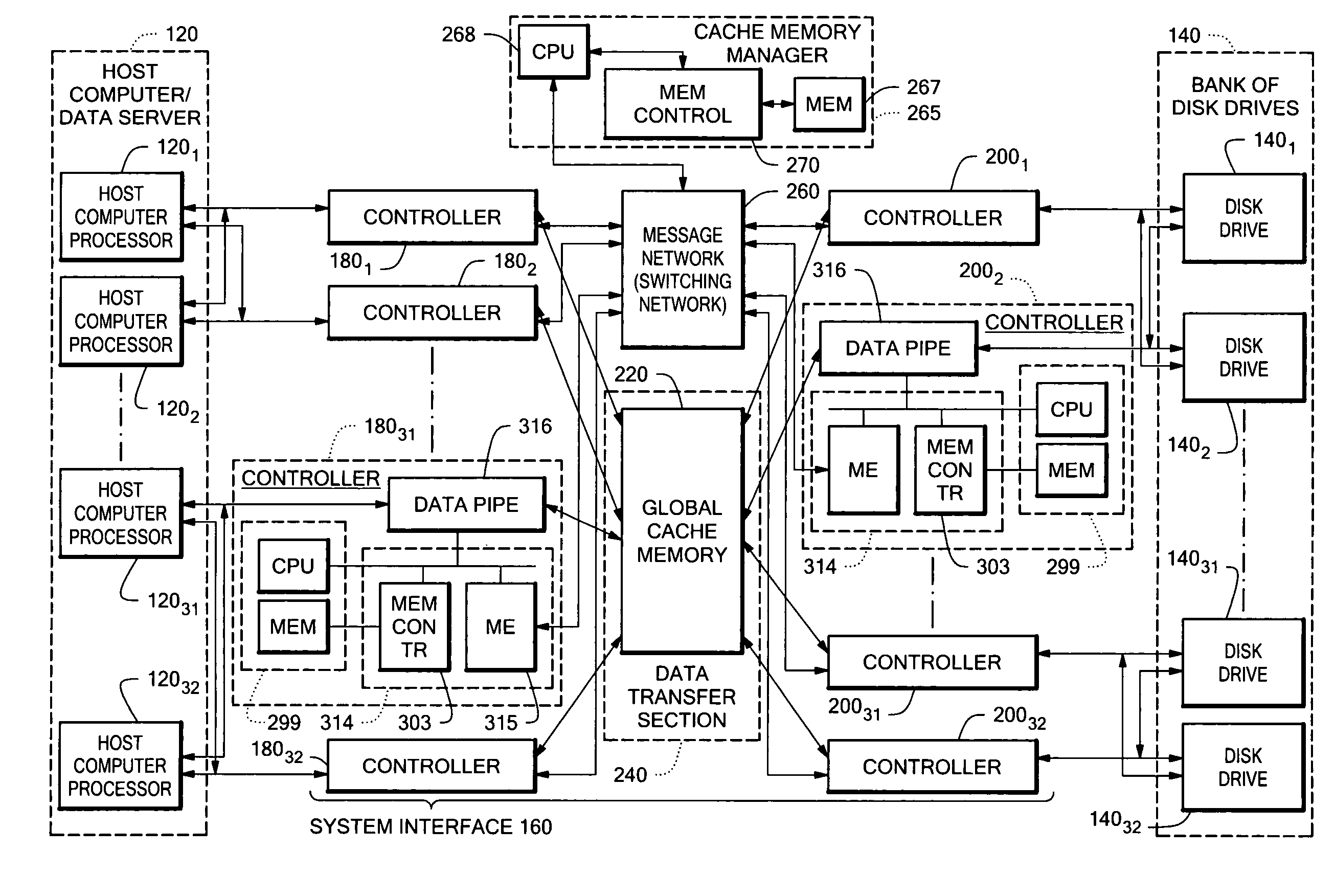
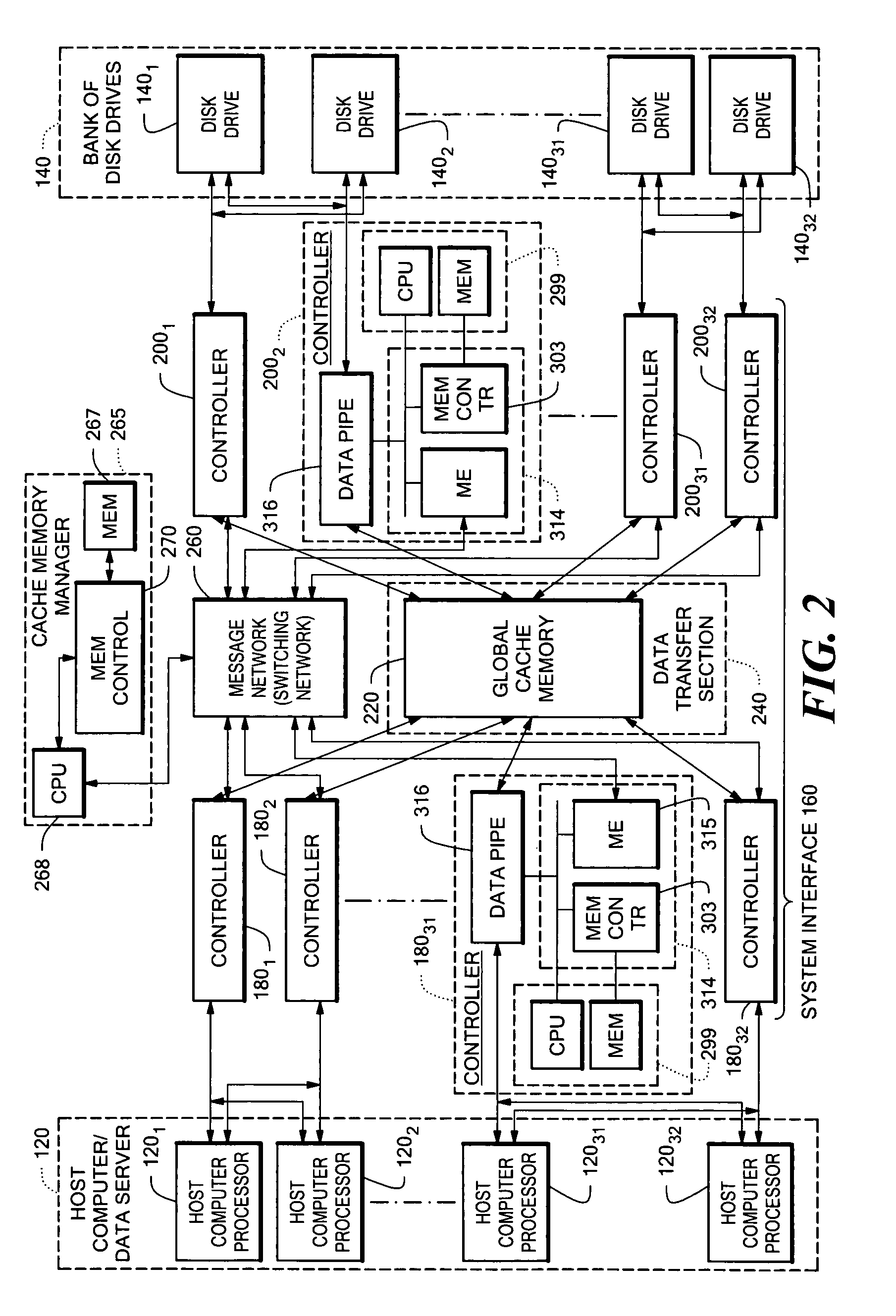
[0050]Referring now to FIG. 2, a data storage system 100 is shown for transferring data between a host computer / server 120 and a bank of disk drives 140 through a system interface 160. The system interface 160 includes: a plurality of, here 32 front-end directors 1801–18032 coupled to the host computer / server 120; a plurality of back-end directors 2001–20032 coupled to the bank of disk drives 140; a data transfer section 240, having a global cache memory 220, coupled to the plurality of front-end directors 1801–18016 and the back-end directors 2001–20016; a messaging network 260, operative independently of the data transfer section 240, coupled to the plurality of front-end directors 1801–18032 and the plurality of back-end directors 2001–20032, as shown; and, a cache memory manager 265.

[0051]It is noted that in the host computer 120, each one of the host computer processors 1211–12132 is coupled to here a pair (but not limited to a pair) of the front-end directors 1801–18032, to pr...


PUM


Abstract

A system interface having: a plurality of front end directors adapted for coupling to a host computer / server; a plurality of back end directors adapted for coupling to a bank of disk drives; a data transfer section having cache memory; a cache memory manager; and, a message network. The cache memory is coupled to the plurality of front end and back end directors. The messaging network operates independently of the data transfer section and is coupled to the plurality of front end and back end. The front end and back end directors control data transfer between the host computer / server and the bank of disk drives in response to messages passing between the front end directors and the back end directors through the messaging network to facilitate data transfer between host computer / server and the bank of disk drives. The data passes through the cache memory in the data transfer section as such data passes between the host computer and the bank of disk drives. The system includes a cache memory manager having therein a memory for storing a map maintaining a relationship between data stored in the cache memory and data stored in the disk drives. The cache memory manager provides an interface between the host computer, the bank of disk drives and the cache memory for determining for the directors whether data to be read from the disk drives, or data to be written to the disk drives, resides in the cache memory. With such an arrangement, the cache memory in the data transfer section is not burdened with the task of transferring the director messaging but rather a messaging network is provided, operative independent of the data transfer section, for such messaging thereby increasing the operating bandwidth of the system interface. Further, the cache memory is no longer burdened with the task of evaluating whether data to be read from the disk drives, or data to be written to the disk drives, resides in the cache memory. The cache memory manager, plurality of front end directors, plurality of back end directors and cache memory are interconnected through a packet switching network.

Description

RELATED CASES[0001]This is a continuation in part of copending patent application Ser. No. 10 / 180,751, filed Jun. 26, 2002, entitled “Data Storage System Having Cache Memory Manager” inventor Kendell A. Chilton.INCORPORATIONS BY REFERENCE[0002]This application incorporates by reference, in their entirety, the following co-pending patent applications all assigned to the same assignee as the present invention:[0003]FILINGSERIALINVENTORSDATENO.TITLEYuval Ofek et al.Mar. 31, 200009 / 540,828Data StorageSystem HavingSeparate DataTransfer SectionAnd MessageNetworkPaul C. Wilson et al.Jun. 29, 200009 / 606,730Data StorageSystem HavingPoint-To-PointConfigurationJohn K. Walton et al.Jan. 22, 200210 / 054,241Data StorageSystem(Divisional of09 / 223,519 filedDec. 30, 1998)Christopher S.Dec. 21, 200009 / 745,859Data StorageMacLellan et al.System HavingPlural FaultDomainsJohn K. Walton-May 17, 200109 / 859,659Data StorageSystem HavingNo-OperationCommandBACKGROUND OF THE INVENTION[0004]This invention relates...

Claims


Application Information

Patent Timeline
Patent Type & Authority Patents(United States)
IPC IPC(8): G06F12/00
CPCG06F12/0866
Inventor WALTON, JOHN K.BAXTER, III, WILLIAM F.CHILTON, KENDELL A.CASTEL, DANIELBERMINGHAM, MICHAELGUYER, JAMES M.
Owner EMC IP HLDG CO LLC
Why Eureka
Eureka Blog
Learn More