Apparatus for monitoring and controlling thread tensioning force in a sewing machine

a technology for sewing machines and threads, applied in the field of sewing machines, can solve the problems of not being able to realize practical and useful proposals, and the thread tensioning apparatus of the typical sewing machine does not provide any means of monitoring or measuring the compression force applied, and achieves accurate, repeatable measurement and monitoring.

Active Publication Date: 2006-10-24
FOLEY MARTIN J
View PDF3 Cites 11 Cited by
  • Summary
  • Abstract
  • Description
  • Claims
  • Application Information

AI Technical Summary

Benefits of technology

[0010]A primary objective of this invention is provision of a thread tensioning apparatus for a sewing machine that provides the operator with a

Problems solved by technology

However, thread tensioning apparatus of the typical sewing machine does not provide any means of monitoring or measuring the compression force applied to the discs or the comparing of the

Method used


Image

  • Apparatus for monitoring and controlling thread tensioning force in a sewing machine
  • Apparatus for monitoring and controlling thread tensioning force in a sewing machine
  • Apparatus for monitoring and controlling thread tensioning force in a sewing machine

Examples


first embodiment

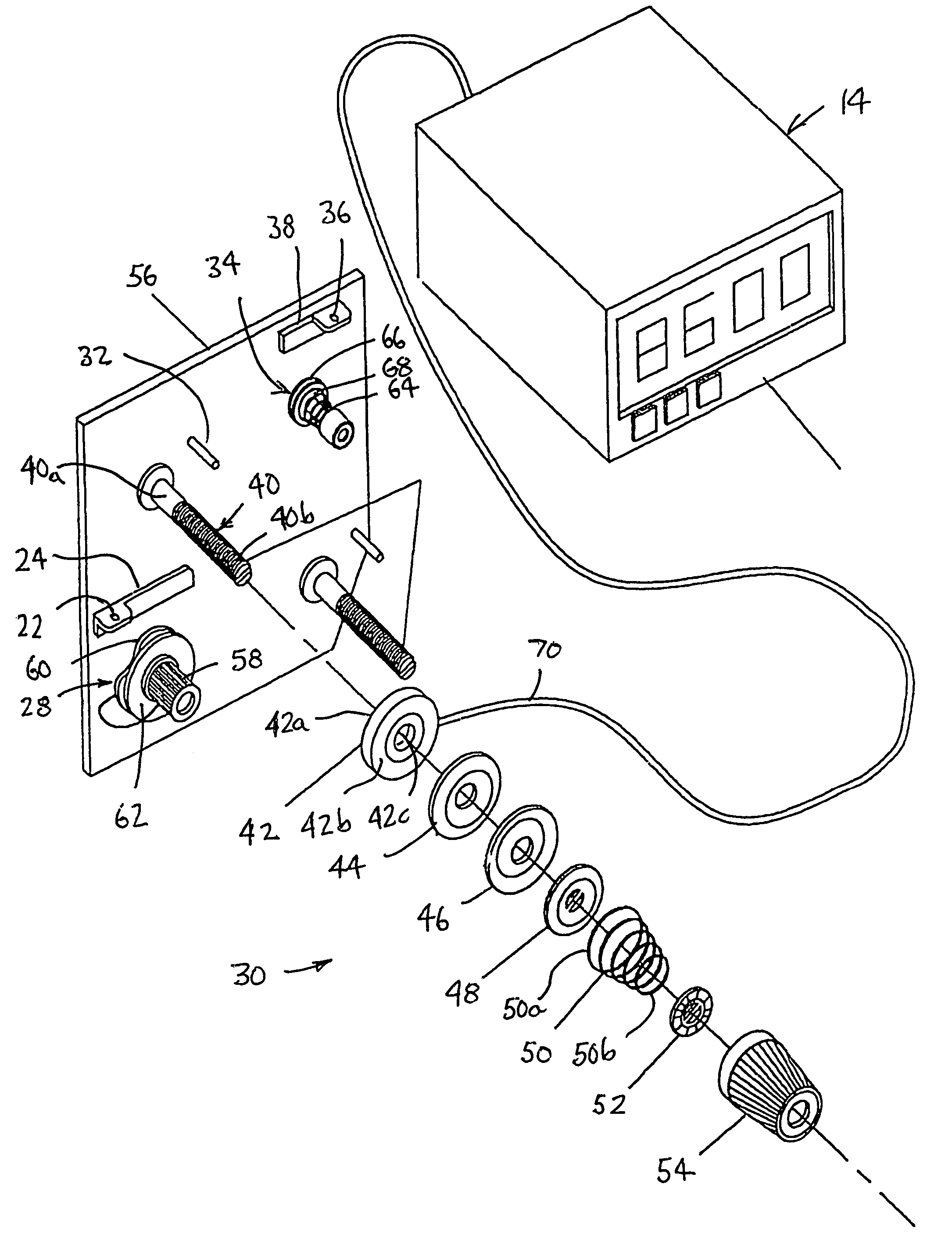
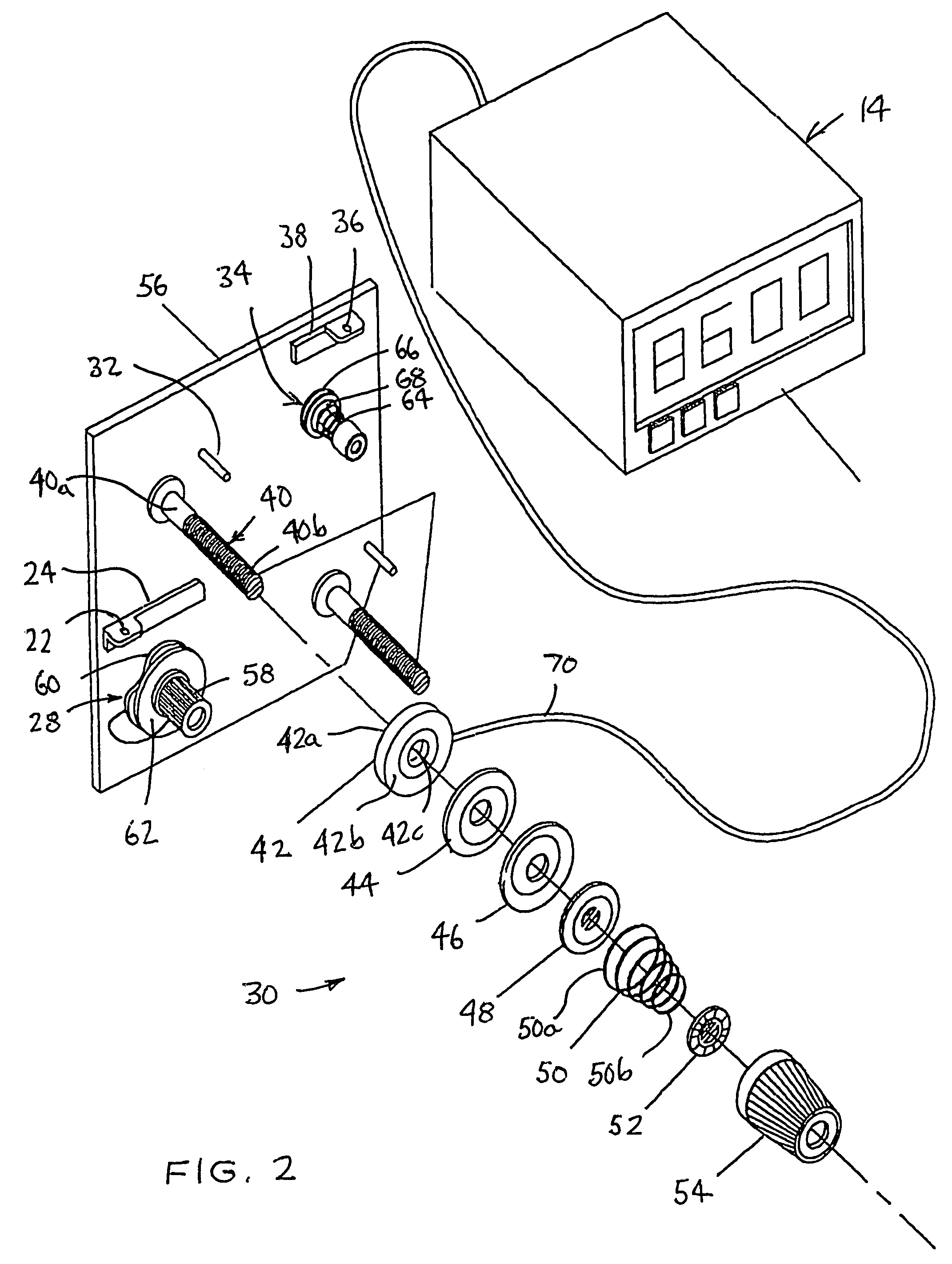
[0048]FIGS. 2 and 3 illustrate a thread tension force adjusting arrangement according to this invention. Sewing thread “T” is passed from the source (not shown) to the needle (not shown) whereby the thread is guided through an aperture 22 of a first guide arm 24, downwardly and around a first disc assembly 28, through a thread tensioning apparatus 30 according to this invention, about a guide pin 32, around a second disc assembly 34, and through an aperture 36 of a second guide arm 38.

[0049]The thread tensioning apparatus 30 includes an axial shaft 40, upon which are mounted a load cell 42, a pair of clamping members or discs 44 and 46, a releasing disc 48, a helical coil spring 50, a knob detent disc 52, and a manipulating knob 54. The shaft 40 has a proximal end 40a fixedly attached to a plate or portion 56 of the housing 20 and a distal end portion 40b spaced from the plate 56 and inwardly of the housing chamber. Preferably, the distal end portion 40b is partially threaded.

[0050]...

second embodiment

[0062]FIGS. 4 and 5 illustrate a thread tension force adjusting arrangement according to this invention. The arrangement is similar to that shown in FIGS. 2 and 3, except that the load cell 42, the spring 50, the knob detent disc 52, and manipulation knob 54 are replaced with a spacer cylinder 70 and a pneumatic actuator 72. The clamping discs 44 and 46 are abutted against the plate 56, and the tension-releasing disc 48 is disposed against the clamping disc 46.

[0063]The spacer 70 is generally cylindrical and has opposite end faces 70a and 70b. The spacer 70 is mounted onto the shaft 40 and positioned so that the end face 70a is juxtaposed against the tension-releasing disc 48.

[0064]The pneumatic actuator 72 includes an actuator body 74 having an abutment face 74a and an actuator rod 76 mounted for axial reciprocating movement relative to the actuator body 74. The forward end 76a of the rod is provided with an internally threaded bore, which is adapted to engage with the threaded end...


PUM


Abstract

A thread tensioning device or apparatus for a sewing machine enables accurate, repeatable measurement and monitoring of the compression forces applied to the thread tensioning discs thereof. The apparatus further includes a visual display or output corresponding to the actual amount of compressive force being applied. The device further includes a comparator, which compares the electrical signal to a predetermined reference value to control or regulate the normal operation of the sewing machine.

Description

CROSS-REFERENCE TO RELATED APPLICATIONS[0001]This application is a completion application of co-pending U.S. Provisional Patent Application Ser. No. 60 / 400,724, filed Aug. 2, 2002, the disclosure of which is hereby incorporated by reference.BACKGROUND OF THE INVENTION[0002]1. Field of the Invention[0003]The following invention relates to sewing machines, and more particularly, to automatic apparatus for monitoring and controlling thread tensioning force in a sewing machine.[0004]2. Description of Prior Art[0005]An existing sewing machine routes the sewing thread through a tensioning apparatus and the thread tension is manually adjusted by an operator, in part, by means of a pair of discs that are compressed against the thread. The correct tension results in a stitch that looks identical on both sides of the material. That is, the knots of the stitches are pulled into the fabric and are no more visible on the top than on the bottom.[0006]To tighten the thread feeding into the needle,...

Claims


Application Information

Patent Timeline
IPC IPC(8): D05B47/04D05B47/06
CPCD05B47/04D05B47/06D05D2205/18
Inventor FOLEY, MARTIN J.
Owner FOLEY MARTIN J
Why Eureka
Try Eureka