Brake system

a technology of brakes and levers, which is applied in the direction of brake systems, wheelchairs/patient conveyances, transportation and packaging, etc., can solve the problems of user in a dangerous situation, extreme difficulty in operating the lever to release the brakes in the state, and inability to start the user's wheel chair, etc., to achieve the effect of reducing size, weight and cost, and high braking performan

Inactive Publication Date: 2006-10-24
AKEBONO BRAKE IND CO LTD
View PDF19 Cites 13 Cited by
  • Summary
  • Abstract
  • Description
  • Claims
  • Application Information

AI Technical Summary

Benefits of technology

[0043]With a view to obtaining higher braking performance on the brake apparatus described in (10) above, the brake apparatuses described in (11) to (13) are such as to indicate preferred combinations of locations, dimensions and configurations of the constituent parts, and with such constructions, the original goal of reduction in size, weight and cost can easily be attained.

Problems solved by technology

Therefore, it is extremely difficult to operate the lever to release the brakes in the state.
Even if the user operates the lever with one of the hands while press holding one of the wheels with the other hand, the wheel chair so stopped on the slope tends to turn on the wheel so press held with the one hand as an axis, and this may put the user in a dangerous situation.
In addition, when the user is so old that he or she does not have enough physical strength, it is easily conceived that he or she cannot start his or her wheel chair on the slope due to a shortage of physical strength required to press hold the wheels.
Consequently, it is extremely difficult for older and heavily handicapped people to keep the wheel chair running on the slope.
However, in either of the brake apparatuses, since the brake force which enables the safe and easy slope starting and climbing is obtained through the construction in which the special members (the arms and the one-way roller) are brought into direct contact with the wheel, there has been caused a problem that the brake apparatus needs to be enlarged in size and weight as the wheels become larger.
In addition, since the brake force is constructed to be obtained through direct contact with the wheels, friction force between the brake member which contacts the surface of the wheel and the wheel changes due to various factors such as the wet surface of the wheel which would result, for example, when the wheel chair is running in the rain, the degree of wear of the wheel (tire) and the air pressure of the wheel, and this change in friction force calls for a change in brake force, leading to a problem that it is difficult to maintain a stable braking performance.
Additionally, since the brake members are exposed outside, there is also caused a problem that the appearance of the wheel chair itself which is equipped with the brake apparatus is aesthetically damaged.

Method used


Image

  • Brake system
  • Brake system
  • Brake system

Examples


first embodiment

[First Embodiment]

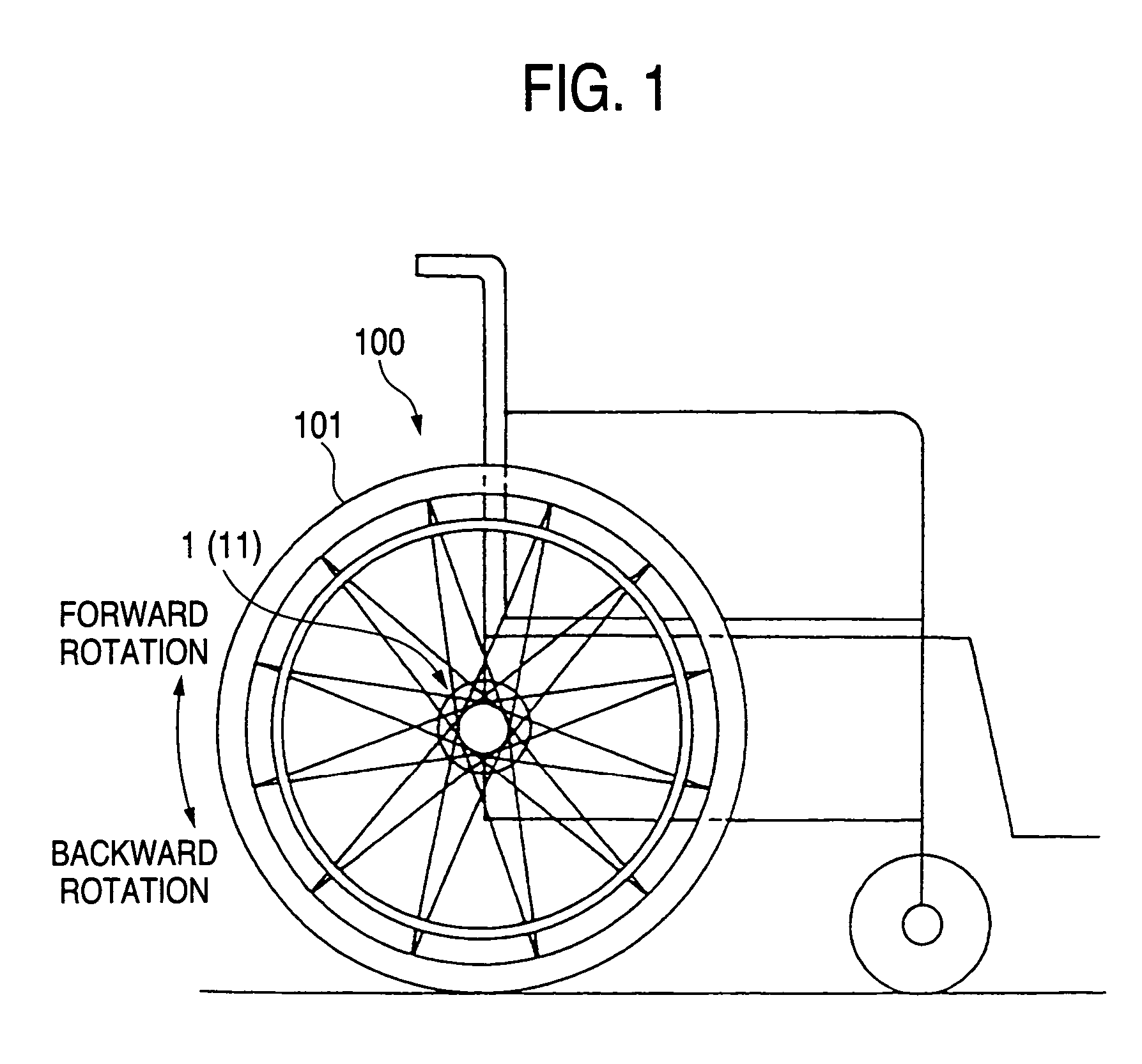
[0070]FIGS. 1 to 5 shows a first embodiment of a brake apparatus according to the invention as being equipped on a wheel chair 100.

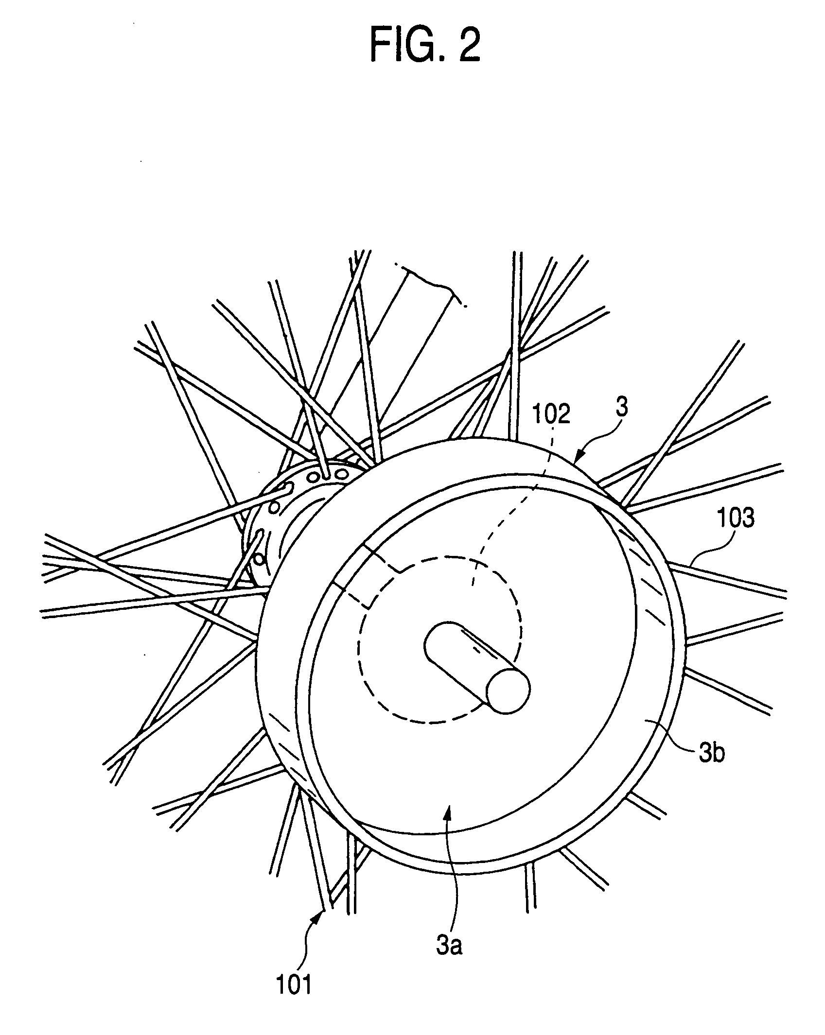
[0071]A brake apparatus 1 shown in this embodiment is a brake apparatus which is generally referred to as a drum brake and includes, as shown in FIGS. 3 to 5, a brake drum 3 which rotates together with a wheel 101, a lock shoe 30 adapted for wedge engagement with an inner circumferential surface of the brake drum 3 when the brake drum 3 rotates backward to thereby generate a brake force, a back plate 5 for supporting the lock shoe 30 within the brake drum 3, a shoe spring 6 for bringing the lock shoe 30 into engagement with the inner circumferential surface of the brake drum 3 and a lock shoe restraining arm 7 for restraining the lock shoe 30 at a position which is spaced apart from the inner circumferential surface of the brake drum, and the brake apparatus 1 is equipped on each wheel 101 of the wheel chair 100.

[0072]Note that the brak...

second embodiment

[Second Embodiment]

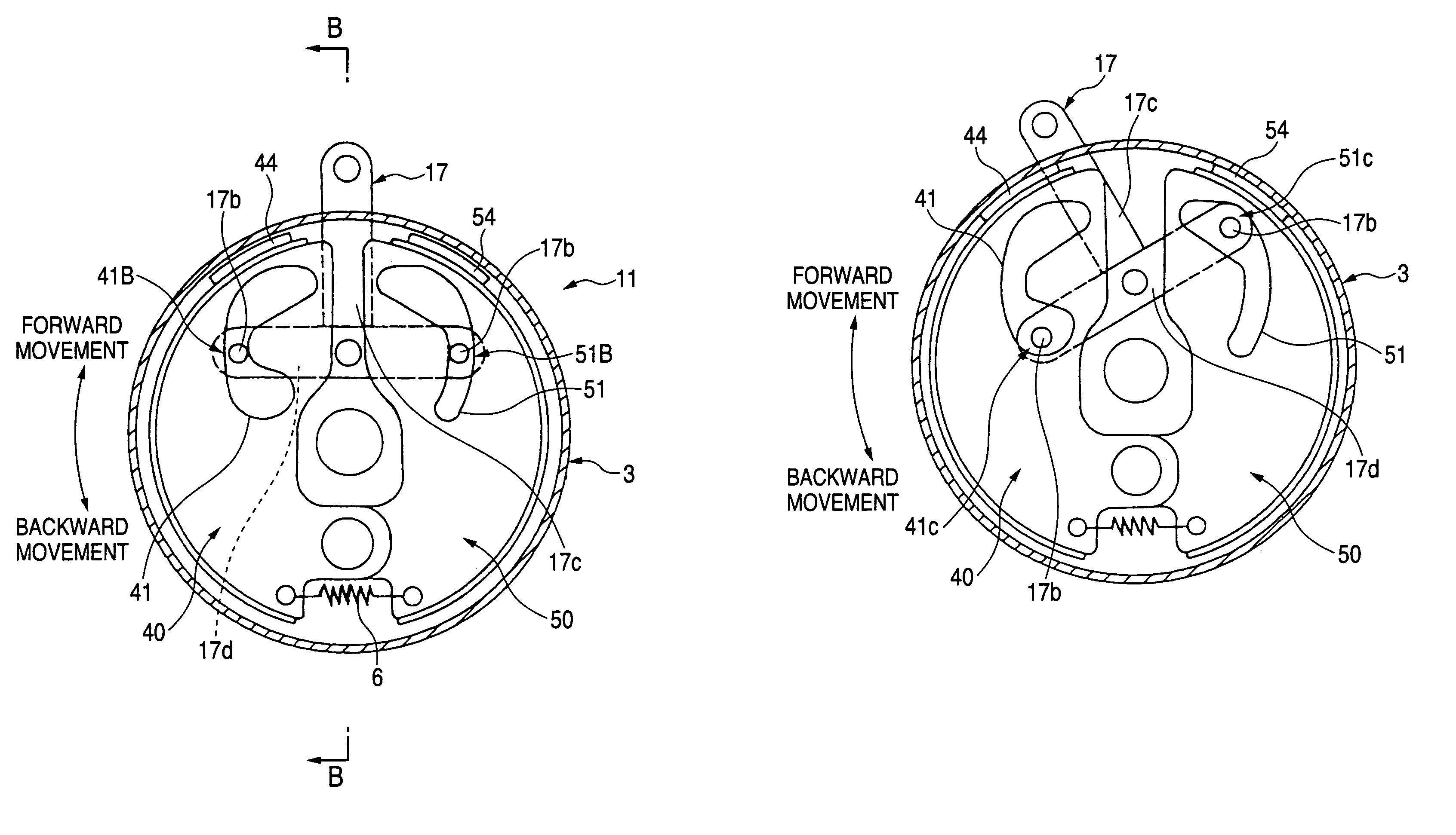
[0099]FIGS. 6 to 9 show a second embodiment of a brake apparatus according to the invention.

[0100]A brake apparatus 11 according to this second embodiment including a slope climbing brake and a parking brake, in a state of installed in the right wheel of the aforesaid wheel chair 100, is shown in which the brake apparatus 11 is viewed from the wheel side.

[0101]In addition, for the sake of better understanding what is in the figures, a back plate 5 is omitted.

[0102]Additionally, since the basic construction of the brake apparatus 11 of the second embodiment follows the basic construction of the brake apparatus 1 of the first embodiment, a description will be made by same reference numbers to substantially same portions.

[0103]As shown in FIG. 6, the brake apparatus 11 provided with the parking brake in addition to the slope climbing brake is constructed so as to have a backward rotation lock shoe 40 which exhibits a brake force when a brake drum 3 rotates backward, ...


PUM


Abstract

An object of the invention is to provide a brake apparatus which can facilitate slope starting and slope climbing and which can be produced small in size and light in weight. In addition, another object of the invention is to provide a brake apparatus which can obtain a stable brake force under any conditions including running in the rain.
The invention provides a brake apparatus in which a restriction is imposed on the rotation of a wheel (101) via a brake drum (3) provided on a rotational shaft of the wheel (101) so as to rotate together with the rotational shaft, the brake apparatus being characterized by comprising a brake shoe (30) for imposing a restriction on the rotation of the brake drum (3) in a forward or backward direction through wedge engagement with an inner circumferential surface of the brake drum (3) when the brake drum (3) rotates either in the forward direction or in the backward.

Description

TECHNICAL FIELD[0001]The present invention relates to a brake apparatus, and more particularly to a brake apparatus which is preferably used on light vehicles such as wheel chairs and baby carriages.BACKGROUND ART[0002]In general, a brake mounted on a wheel chair is constructed such that a swingable lever is provided on a frame of the wheel chair so that part of the lever is pressed against a wheel to apply brakes. Note that since wheels of a wheel chair are constructed to rotate independently, brakes are designed to be applied to the wheels simultaneously.[0003]Incidentally, when a user attempts to start a wheel chair on a slope while being seated therein, an operation is required of releasing brakes while rotating both wheels. However, both hands of the user are occupied to rotate the both wheels in this state. Therefore, it is extremely difficult to operate the lever to release the brakes in the state.[0004]Even if the user operates the lever with one of the hands while press hol...

Claims


Application Information

Patent Timeline
Patent Type & Authority Patents(United States)
IPC IPC(8): B62B5/04A61G5/10B60T7/12F16D51/36F16D51/60
CPCA61G5/1027B60T7/122B62B5/048F16D51/20F16D51/60A61G5/1008A61G5/101A61G5/1035A61G2005/1054A61G2005/1086B62B5/0438A61G5/1054A61G5/1086
Inventor IKEGAMI, HIROSHIFURUKAWA, HITOSHITERASHIMA, SHINICHIMASHIKO, MINORU
Owner AKEBONO BRAKE IND CO LTD
Why Eureka
Try Eureka