Flame simulating device

a technology of simulating devices and flames, which is applied in the direction of lighting support devices, lighting and heating apparatuses, light source combinations, etc., can solve the problems of flame displays that are relatively poor imitations of real flames, cannot be easily setup and maintained without, and real flame sources are easily extinguished

Inactive Publication Date: 2006-10-24
WAINWRIGHT HARRY LEE
View PDF7 Cites 125 Cited by
  • Summary
  • Abstract
  • Description
  • Claims
  • Application Information

AI Technical Summary

Benefits of technology

[0012](d) each of said first, second and third light sources being sequentially activated such that the surface of said shell is illuminated and produces an animated flame effect.
[0017](d) each of said light sources being sequentially activated such that the surface of said shell is illuminated and produces an animated flame effect.

Problems solved by technology

Conventional flame sources require lighting with matches or the like, and when lit, represent a serious fire hazard, especially when unattended as is the case in commercial settings (e.g. restaurants, stores etc.) Furthermore, real flame sources (e.g. candles) present other personal injury and collateral damage challenges (e.g. dripping wax on people and / or upholstery etc.) Finally, real flame sources are easily extinguished (e.g. by air currents etc.) and accordingly cannot be easily setup and maintained without constant monitoring.
However, such attempts result in flame displays that are relatively poor imitations of a real flame.
In addition, such devices require substantial energy and require frequent battery replacement.

Method used


Image

  • Flame simulating device
  • Flame simulating device
  • Flame simulating device

Examples


Embodiment Construction

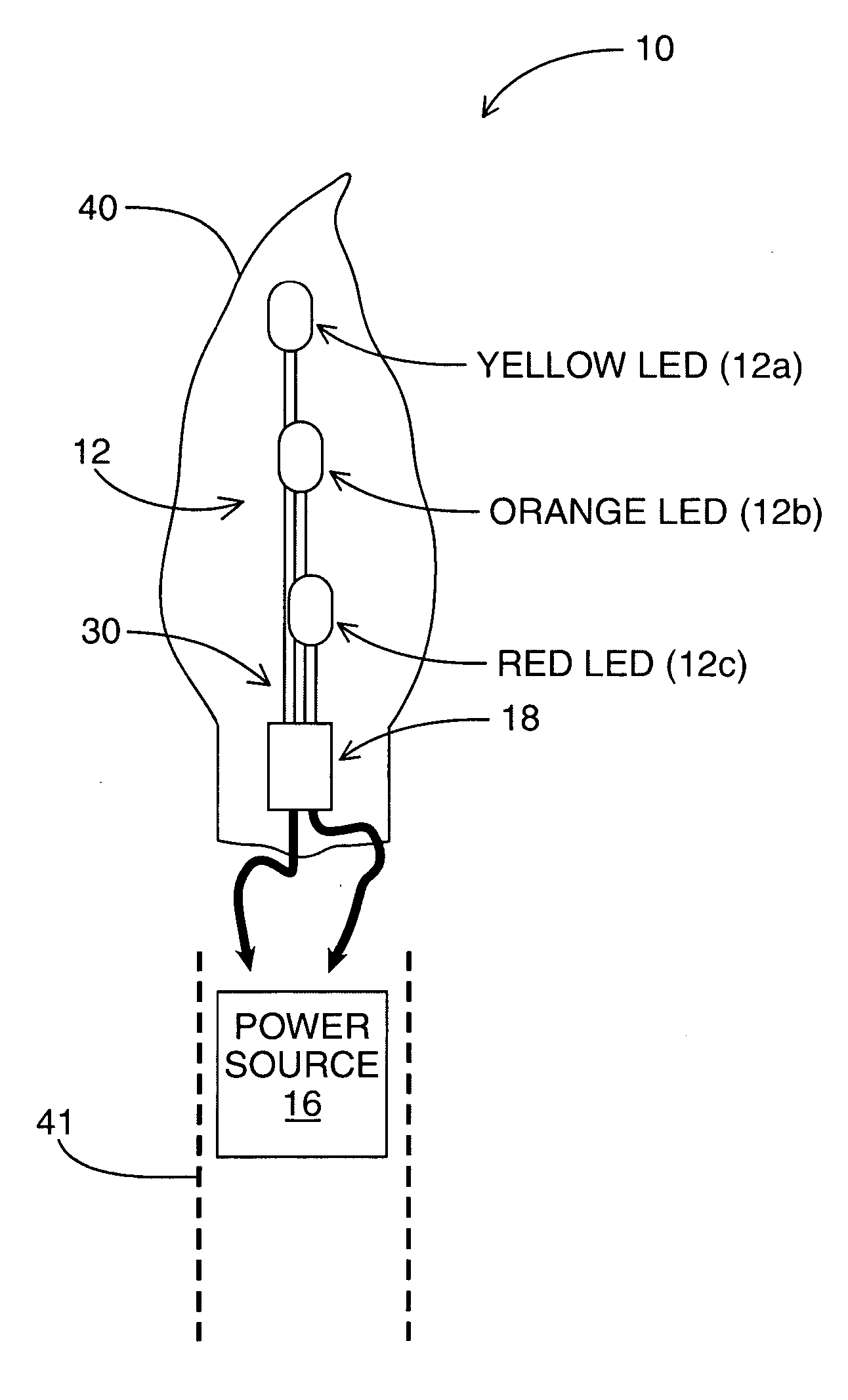
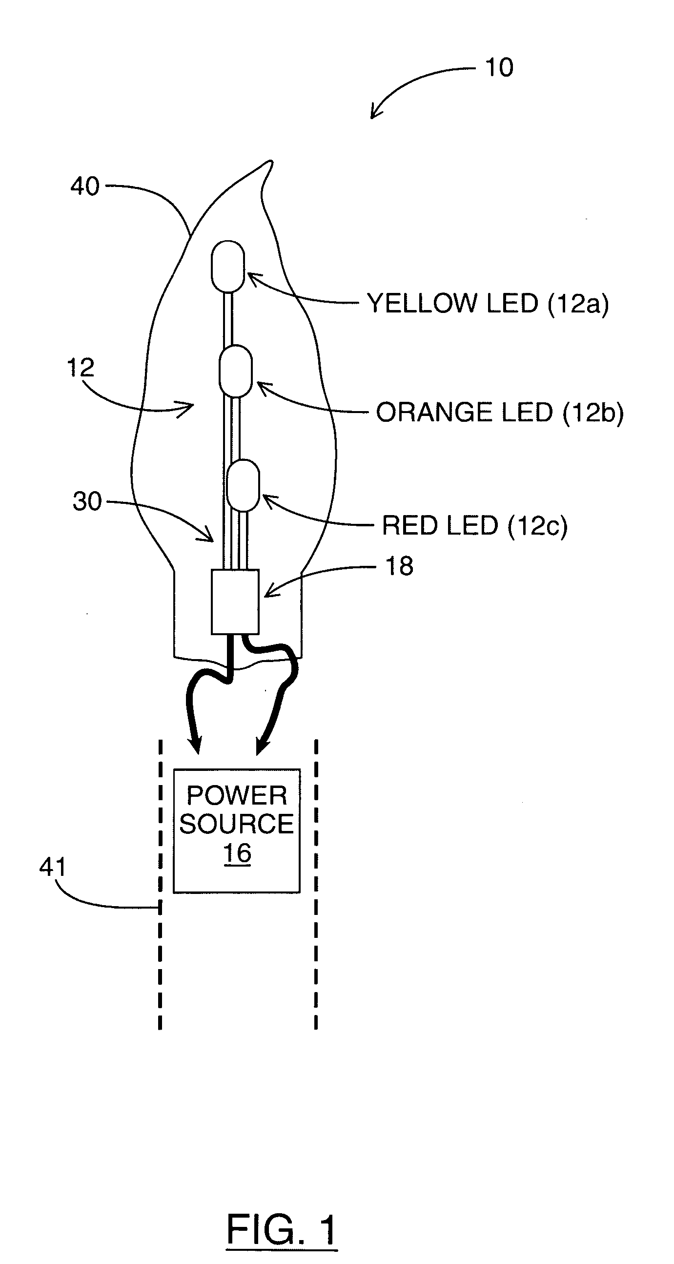
[0026]Referring to FIG. 1, illustrated therein is a flame simulating device 10 made in accordance with a preferred embodiment of the present invention. Flame simulating device 10 consists of an LED lighting assembly 30 that is incased in a substantially translucent shell 40. LED assembly 30 consists of an LED array 12, a power source 16, light source driving circuit 18. Light source driving circuit 18 is designed to allow a maximum of one LED from LED array 12 to be on at any particular time. Also as shown, flame simulating device 10 is also adapted to fit within the top of a base 41. The combination of LED assembly 30 and shell 40 of flame simulating device 10 provides realistic flame lighting effects as will be described.

[0027]Shell 40 is substantially translucent in order to allow a substantial amount of light from LED array 12 to penetrate the surface of shell 40 such that visible lighting effects are provided on the surface of shell 40. Shell 40 is preferably flame-shaped (FIG....


PUM


Abstract

A flame simulating device includes a substantially translucent shell having a hollow interior, a plurality of colored light sources, positioned within the hollow interior of said shell and a light source driving device for selectively activating each of said plurality of light sources. Each of the light sources are alternately and individually activated to have active periods and such that the surface of said shell is illuminated to produce an animated flame effect. In one example implementation, yellow, orange and red LEDs are positioned at varying heights within the flame-shaped shell and activated on and off in a sequence that follows a set of color transition rules in order to provide a close simulation of the flickering of a flame. During their active periods, LEDs are blinked on and off to conserve power.

Description

[0001]This application claims the benefit under 35 U.S.C. 119(e) of U.S. Provisional Application No. 60 / 468,185, filed May 6, 2003.FIELD OF THE INVENTION[0002]This invention relates to display devices and particularly to flame simulating devices.BACKGROUND OF THE INVENTION[0003]Conventional flame sources require lighting with matches or the like, and when lit, represent a serious fire hazard, especially when unattended as is the case in commercial settings (e.g. restaurants, stores etc.) Furthermore, real flame sources (e.g. candles) present other personal injury and collateral damage challenges (e.g. dripping wax on people and / or upholstery etc.) Finally, real flame sources are easily extinguished (e.g. by air currents etc.) and accordingly cannot be easily setup and maintained without constant monitoring.[0004]There are a variety of flame imitation novelty products that utilize various methods to simulate a real flame for display purposes such as those disclosed in U.S. Pat. Nos. ...

Claims


Application Information

Patent Timeline
Patent Type & Authority Patents(United States)
IPC IPC(8): F21V9/00F21S4/00F21S10/04H05B37/02H05B44/00
CPCF21S6/001F21S10/04H05B33/0803H05B33/0818H05B33/0857H05B37/029Y10S362/81F21W2121/00F21Y2115/10F21Y2113/13H05B45/20H05B47/155H05B45/30
Inventor WAINWRIGHT, HARRY LEE
Owner WAINWRIGHT HARRY LEE
Why Eureka
Try Eureka