Optical Symbol, Article to which the Optical Symbol is Attached, Method for Attaching Optical Symbol to Article, Optical Symbol Decoding Method, Related Device, and Related Program

a technology of optical symbols and optical symbols, applied in the field of optical symbols, can solve the problems of difficult for the conventional reading technique to handle such a 1d color bit code, difficult to achieve the effect of preventing data falsification and obtaining flexibility in design

Active Publication Date: 2009-12-24
B CORE INC
View PDF16 Cites 15 Cited by
  • Summary
  • Abstract
  • Description
  • Claims
  • Application Information

AI Technical Summary

Benefits of technology

[0107]According to the optical symbol of the present invention, the order of configuration cells can be specified by tracing configuration cells. Since data is expressed by combination of colors or the like of the configuration cells, a code system which does not exert an influence on reading of data even when the size of the configuration cell changes is obtained.
[0108]Since flexibility of the relative positional relation among groups of cells constructing a symbol is high, the symbol can be used also for an item whose surface is soft.
[0109]For example, a symbol can be directly printed on food such as soft meat by using food colorants. A symbol can be also directly printed on cloth and a soft item.
[0110]In a conventional optical barcode, a symbol is attached to an item by a process of affixing a seal or the like, and there is not a little possibility that data is falsified by replacing with another seal or the like. In contrast, according to the present invention, a symbol can be directly printed even on a soft item. Therefore, it is significantly difficult to replace the symbol with another symbol. As a result, according to the invention, data falsification can be prevented.
[0111]In the optical symbol and the code system using the optical symbol according to the invention, a symbol is constructed by linearly arranging a plurality of cells. As long as the symbol is linear, it may be straight or curved. Therefore, a symbol having flexibility in design can be obtained.
[0112]As described above, in the present invention, a group of cells satisfying the conditions of a “marking pattern” of the 1D color bit code in the entire image data is extracted from the “background image” based on the characteristics. Therefore, a code can be recognized without using an auxiliary sign such as a “cutout mark” like in a conventional two-dimensional barcode.

Problems solved by technology

There is consequently a problem that the optical code using colors is susceptible to deterioration in color, printing unevenness, illumination light, and the like.
However, since the size and shape of an area occupied by a predetermined color are not constant, it is difficult for the conventional reading technique to handle such a 1D color bit code.
Even in the case where only the “marking pattern” floats in the air (such as the case where the marked object to be marked is a transparent one, or the two-dimensional barcode is hung by a string or the like), it is usually unavoidable that a background is captured together with the marking pattern.
On the other hand, a predetermined width (length of thick and thin bars) is necessary for the “marking pattern” in the barcode, and when the thickness is extremely small or large or in the case where arranged bars are curved, it is very difficult to perform decoding.
As a result, the possibility that an entire single code symbol cannot be captured at once increases.
In such cases, since the code symbol cannot be captured in a single screen, it is difficult to restore data.

Method used


Image

  • Optical Symbol, Article to which the Optical Symbol is Attached, Method for Attaching Optical Symbol to Article, Optical Symbol Decoding Method, Related Device, and Related Program
  • Optical Symbol, Article to which the Optical Symbol is Attached, Method for Attaching Optical Symbol to Article, Optical Symbol Decoding Method, Related Device, and Related Program
  • Optical Symbol, Article to which the Optical Symbol is Attached, Method for Attaching Optical Symbol to Article, Optical Symbol Decoding Method, Related Device, and Related Program

Examples


first embodiment

[0171]A preferred embodiment of the present invention will be described hereinbelow with reference to FIGS. 1 to 13.

[0172]In this embodiment, a code using an optical symbol having a form in which cells are placed linearly. The optical symbol is a symbol in a plane shape and is attached to various items.

Cell (Configuration Cell) and End-Point Cell

[0173]An optical symbol of this embodiment is constructed by cells and end-point cells. A cell is a range / area to which a single color is assigned and can be formed in various shapes such as circle, square, triangle, and the like. An optical symbol is formed by arranging these cells linearly.

[0174]The end-point cell is a cell positioned at an end point of an optical symbol made by a group of cells connected linearly. In this embodiment, the end-point cell is an area / range to which a color different from the color assigned to a cell other than the end-point cell is assigned. As will be described later, according to a combination (of colors) w...

example 1-1

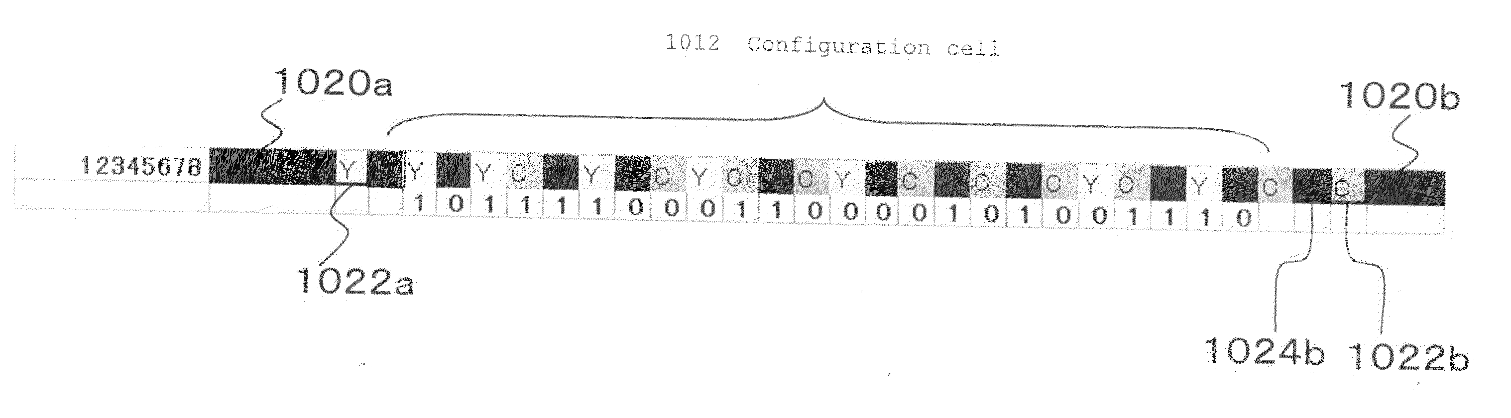
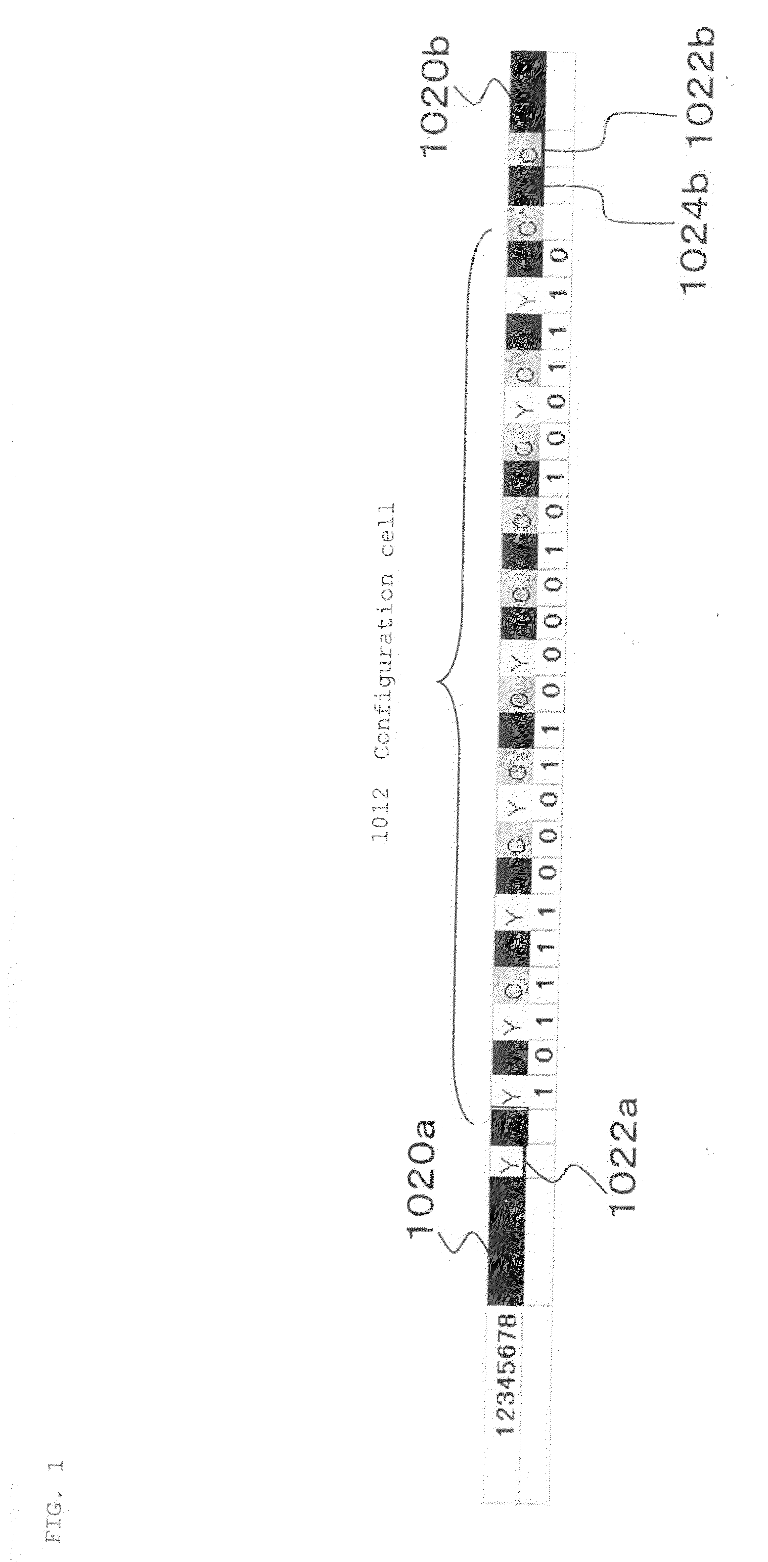
[0178]FIG. 1 shows an example of an optical symbol 10 expressing numerical values “12345678” (in decimal). In the example 1-1, is represented as “101111000110000101001110” in binary. Therefore, in the example 1-1, the binary numbers “101111000110000101001110” are shown.

[0179]In FIG. 1, squares to which Y (representing yellow), M (representing magenta), and C (representing cyan) or the like are assigned are cells 1012. By connecting a plurality of cells 1012, an optical symbol 1010 is constructed.

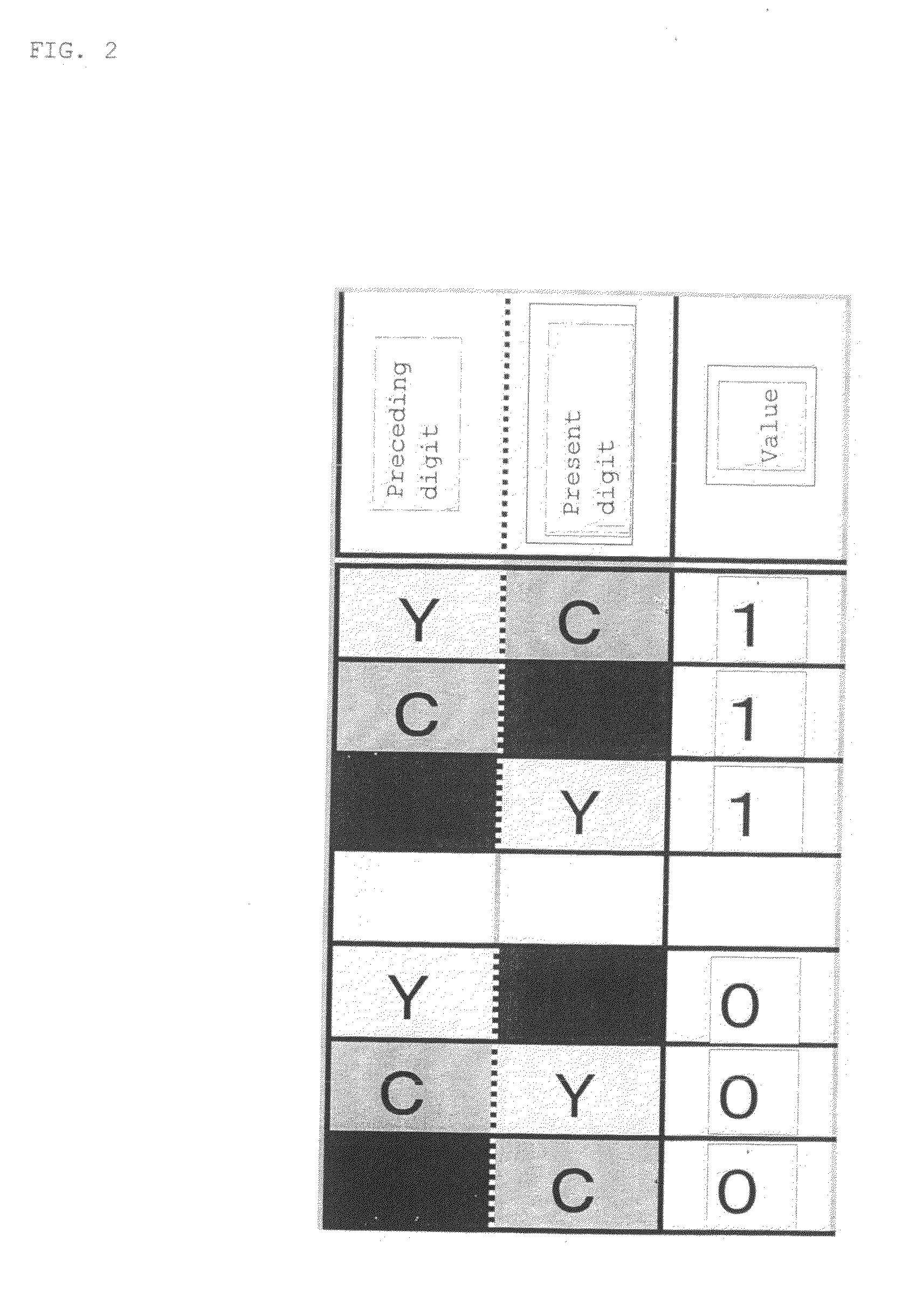
[0180]In the example 1-1, the elements “0” and “1” of the binary notation are expressed as in a table of FIG. 2. Specifically, “1” and “0” are not assigned to colors but are assigned to shifts of colors. In the example 1-1, black, cyan (C), magenta (M), and yellow (Y) are used, and shifts of colors from Y to C, from C to M, and from M to Y indicate “1” (see FIG. 2). Shifts of colors from Y to M, from C to Y, and from M to C indicate “0” (see FIG. 2).

[0181]That is, the value of the present di...

example 1-2

[0200]FIG. 6 shows an example of directly encoding numerals, alphabets, and the like (without converting to binary numbers).

[0201]FIG. 6 shows three kinds of conversion tables showing how numerals and alphabets are converted. Three kinds of conversions, a conversion starting from C, a conversion starting from M, and a conversion starting from Y are prepared according to the color of the first cell 1012.

[0202]Specifically, there are three ways of expressing “0”: arranging the cell 1012 in the order of “YMYCM”, arranging the cell 1012 in the order of “MCMYC”, and arranging the cell 1012 in the order of “CYCMY”. One of the three ways is selected according to the color of the preceding cell 1012, one of the three ways is selected.

[0203]Also in the method of the example 1-2 shown in FIG. 6, the code system is determined based on the color change direction of the neighboring cell 1012. FIG. 7 shows an explanatory diagram showing the relations of color change directions. As shown in FIG. 7...


PUM


Abstract

It is possible to linearly arrange cells and indicate particular data in the order of colors of respective sells. A code system uses an optical symbol decoding method capable of reading the color arrangement if the arrangement continuity and the linear shape are maintained. The data expression method may be other than “the order of colors.” For example, it is possible to employ a method for allocating a numeric value to each of the colors by one-to-one correspondence (R=0, B=1, etc.), a method for allocating data by a color transition (“CM”=“MY”=“YC”=0, “CY”=“YM”=“MC”=1, etc.), a method for allocating data for a combination of colors, and the like.

Description

TECHNICAL FIELD[0001]The present invention relates to an optical code to be attached to an item for information processing. More particularly, the invention relates to an optical symbol used in the optical code, a method of attaching the optical symbol to an item, and a decoding method.[0002]The invention further relates to an optical recognition code. More particularly, the invention relates to an optical recognition code reading technique (symbol cutout technique).[0003]The invention also relates to an optical recognition code. More particularly, the invention relates to an efficient data restoring method for an optical recognition code called a 1D color bit code (Japanese Patent Application No. 2006-196705) proposed by the inventors of the present invention. The invention also provides a specification suitable for efficient data restoration. That is, the present invention also relates to a coding technique of an optical recognition code.BACKGROUND ARTSBackground Art 1[0004]Variou...

Claims


Application Information

Patent Timeline
Patent Type & Authority Applications(United States)
IPC IPC(8): G06K7/12G06K19/06
CPCG06K1/123G06K7/10722G06K2019/06225G06K7/1443G06K19/06018G06K7/14G06K7/10G06K19/06
Inventor KIMURA, AKITERUMATSUDA, MASAYUKIKANDO, KUNIO
Owner B CORE INC
Why Eureka
Try Eureka