Attachment devices and methods for a dental appliance

a technology of dental appliances and attachment devices, which is applied in the field of orthodontics, can solve the problems of reducing the visibility and awareness of patients, reducing the use of conventional braces, so as to achieve the effect of adequate force and appropriate physical leverag

Inactive Publication Date: 2006-10-24
ALIGN TECH
View PDF169 Cites 98 Cited by
  • Summary
  • Abstract
  • Description
  • Claims
  • Application Information

AI Technical Summary

Benefits of technology

[0009]The present invention provides improved devices, systems and methods for removably attaching a dental positioning appliance to the dental features of a patient during orthodontic treatment. Such removable dental positioning appliances usually comprise an elastic polymeric shell having a cavity for receiving at least some of a patient's teeth and are often preferred over conventional braces for tooth repositioning due to comfort, appearance and ease of use. These appliances function by applying force to specific surfaces of the teeth or dental features to cause directed movement. However, the type of movement and level of force applied is usually dependent on the surface characteristics and positions of the dental features. In many cases, the native tooth surface(s) and other dental features of a patient are inadequate to provide sufficient anchoring or to impart sufficient force on the teeth to be repositioned. To overcome these limitations, the present invention uses one or more attachment devices which may be attached to preselected attachment points on the teeth or dental features to provide the appropriate physical leverage. Specific design and location of these attachment devices may provide newly achievable and / or more effective repositioning forces, anchoring ability and appliance retention. The systems and methods of the present invention provide the design, production and use of such attachment devices with removable dental positioning appliances in orthodontic treatment.
[0010]The use of attachment devices in combination with removable dental positioning appliances provides the patient with the benefits of removable appliances while retaining the ability to extrude, rotate, and otherwise manipulate teeth as with conventional braces. Like conventional braces, attachment devices may be bonded to the surface of the teeth in order to provide physical features which facilitate the application of controlled force. The attachment devices of the present invention may have a very simple construction, in some instances being only a bump, bead, wedge, or other body or structure which can be fixedly attached to the surface of a tooth or other dental feature in order to transmit force generated by the dental positioning appliance to the dental feature and / or to anchor the positioning appliance to teeth in order to permit the appliance to apply forces elsewhere in the patient's teeth. In such instances, the attachment device acts simply as a handle or lever to assist in the transmission of force between the teeth and the dental positioning appliance. In other instances, the attachment device may feature a hook, similar in design to those used for mounting elastic bands. The hook may be engaged with a number of ligatures, bands, filaments, coils or other connecting members to effect repositioning of the teeth, usually in combination with the dental positioning appliance. The hook may serve as an anchor in the repositioning of other teeth, or it may serve as a point of purchase to apply directed force to the surface of the tooth to which it is bonded.
[0017]Similarly, a malleable material may be molded into a desired form and polymerized by exposure to an environmental condition or stimulus. Such polymerization may permanently hold the material in the desired form. This may be useful in both constructing the attachment device and bonding the device to a dental surface. For example, malleable material may be inserted in a mold of an attachment device. Polymerization, as described above, may result in a rigid attachment device in the molded form. In a preferred embodiment, the mold of the attachment device may be an impression in the wall of an elastic positioning appliance. This may ensure proper surface geometry for association between the attachment device and the appliance. Likewise, polymerization of the material while the appliance is in place over the dental features may simultaneously bond the attachment device to the dental feature. This may ensure proper alignment of the attachment device and the receiving impression in the appliance, and it may also preclude the need for additional bonding materials.
[0021]In a fifth aspect of the present invention, an additional method is provided to produce and / or bond an attachment device to a dental feature. Two preferred embodiments are applicable for use with any dental appliances. The first embodiment involves a multi-tooth template which may be used to produce and / or bond an attachment device to a dental feature. The multi-tooth template may be thin and flexible to fit over multiple dental features at once, allowing multiple attachment devices to be placed at the same time. Receptacles may be present in the template to receive a polymerizing material. When the template is inserted and seated in position in the oral cavity, the polymerizing material will be in contact with the dental surface and will be in the proper position. The material may be polymerized by any means, typically by an external stimulus or environmental condition. Polymerization may simultaneously harden the material and bond the material to the dental surface. Upon removal of the template, the formed attachment device may remain in place on the dental surface. This method may be similar or identical to casting with polymerizing material and computer-aided casting with polymerizing material, however it may differ in that the template may not be used as the repositioning appliance. This difference may afford the use of template designs that are not applicable to repositioning appliances. For example, the template may be comprised of a material that is unsuitable for a repositioning appliance, or it may contain additional design features, such as handles, that would interfere with such usage. Similarly, the template may be fabricated from a mold of the patient's present tooth configuration, rather than the tooth configuration prescribed by an elastic positioning appliance. This may facilitate the method of attachment device production and / or bonding due to the closer fit of the template to the tooth configuration.
[0023]Single-tooth and multi-tooth templates may allow the production and placement of one or more attachment devices to a dental feature independent of the geometry of certain adjacent dental features. Thus, a template may be used throughout various stages of orthodontic repositioning treatment. This may be useful to replace an attachment device which has broken off mid-treatment or to place new attachment devices throughout treatment. As described above, at least one receptacle may be present in the template to receive a polymerizing material. When the template is inserted and seated in position in the oral cavity, the polymerizing material will be in contact with the dental surface and will be in the proper position. The material may be polymerized by any means, typically by an external stimulus or environmental condition. Polymerization may simultaneously harden the material and bond the material to the dental surface. Upon removal of the template, the formed attachment device may remain in place on the dental surface. Alternatively, templates may be used to bond any attachment device to a dental feature surface. For example, a pre-fabricated attachment device may be bonded to a surface with the use of a template. An attachment device may be inserted in a receptacle of a template, adhesive applied to the base of the attachment device and the template applied to the dental surface. After bonding has occurred, the template may be removed. Thus, the template may provide proper positioning and orientation. Likewise, a template may be used to form an attachment device using a polymerizing material, and then used again to bond the attachment device to a dental surface.
[0024]In a sixth aspect of the present invention, a method is provided to improve the production of templates or elastic positioning appliances. In a preferred embodiment, additional structures are provided in the mold of the dental feature with desired attachment device. The structures may be of any geometry and are typically placed near the gingival surface. When a template or appliance is thermoformed over the mold and additional structures, the structures provide a protrusion which aids in drawing the template or appliance from the mold. The protrusion may then be removed before use.

Problems solved by technology

In many cases, the native tooth surface(s) and other dental features of a patient are inadequate to provide sufficient anchoring or to impart sufficient force on the teeth to be repositioned.
Thus, the infrequency of the device, in addition to the size, also reduces its visibility and awareness to the patient.
Likewise, the attachment device may be bonded to any surface of the teeth, including lingual surfaces which would allow the devices to be largely unnoticeable to others.
Brackets used with conventional braces, such as those used to support elastic bands or headgear, are limited in design and therefore application of use.
Generally, these attachment devices have a large profile, protruding 2–4 mm, which is not conducive to use with elastic positioning appliances or other devices designed to be removably positioned over the attachment device.
Likewise, their surface geometry is limited to a few prescribed functions which are specific to use with conventional braces.
Thus, they are not adequately capable of providing functions necessary to the present invention, such as removably attaching a dental positioning appliance.

Method used


Image

  • Attachment devices and methods for a dental appliance
  • Attachment devices and methods for a dental appliance
  • Attachment devices and methods for a dental appliance

Examples


first embodiment

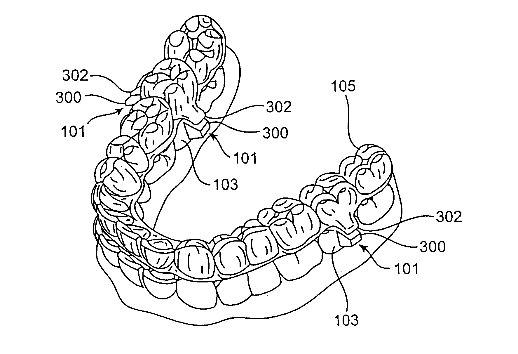
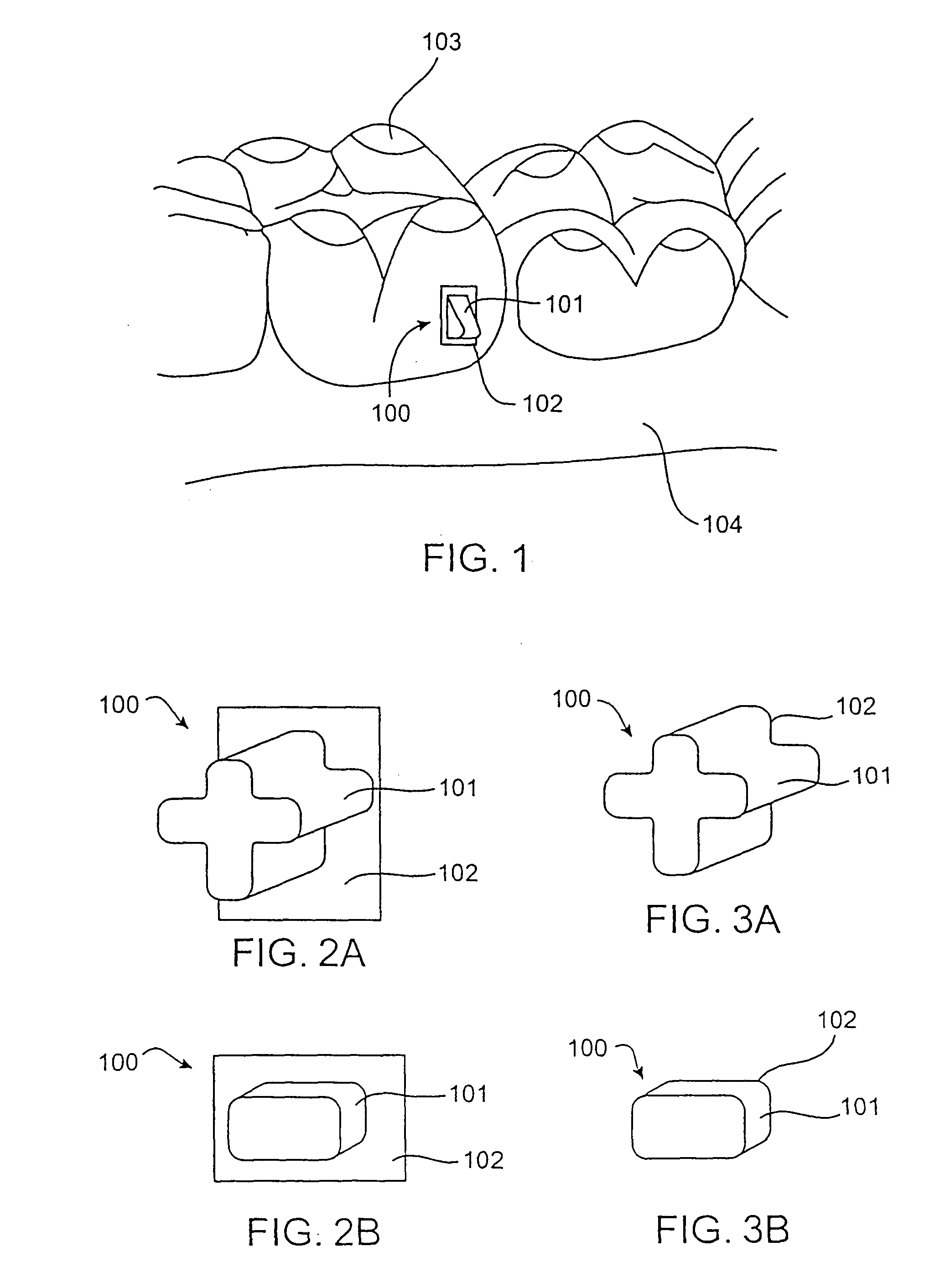
[0058]Two additional methods are provided to produce and / or bond an attachment device 100 to a dental feature, such as a tooth 103. These embodiments are applicable for use with any dental appliance. The first embodiment involves a multi-tooth template. The multi-tooth template may be similar or identical to an elastic repositioning appliance, and it may be used for casting with polymerizing material and computer-aided casting with polymerizing material, as described above. However, it may differ in that the template may not be used as the repositioning appliance. Therefore, multi-tooth template designs may include features that are not applicable to such use. For example, in FIG. 16, one embodiment depicts a type of handle 403 with which to easily place and remove the multi-tooth template 404. As shown, the template 404 may contain receiving cavities 401 for only a select portion of teeth and it may include negative impressions 302 for attachment devices 100 on more than one tooth ...

second embodiment

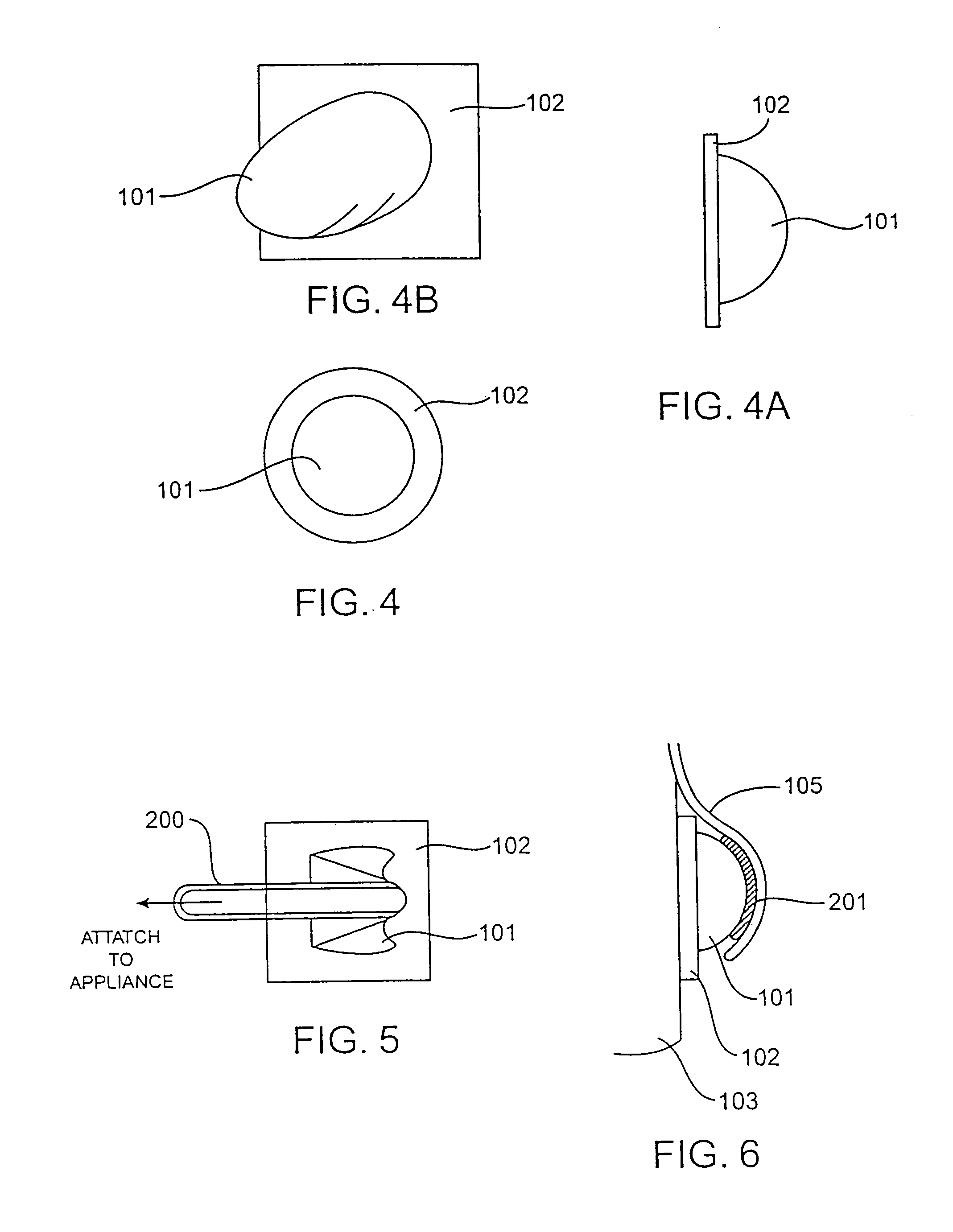
[0059]The second embodiment involves a single-tooth template. The single-tooth template is similar to the multi-tooth template 404, however it may be more rigid as it is designed to fit over a single dental feature. As shown in FIG. 17A, one embodiment may contain a portion of a receiving cavity 401 which conforms to a portion of the surface of the target tooth 103. It may also contain a type of handle 403 to aid in placement of the single-tooth template 405. Production and bonding of an attachment device 100 to the tooth 103 may be accomplished by casting with polymerizing material or computer-aided casting with polymerizing material. Similarly, an additional embodiment of a single-tooth template 405 may be seen in FIG. 17B. Here the template 405 may be thin and flexible to conform to a portion of a dental feature. It may contain adhesive ring 406 around the negative impression 302 of the attachment device 100. The adhesive ring 406 will hold the template 405 in place on the dental...


PUM


Abstract

The present invention provides improved systems and methods for removably attaching a dental positioning appliance to the dental features of a patient during orthodontic treatment. These appliances function by applying force to specific surfaces of the teeth or dental features to cause directed movement. The application of force is improved by the use of one or more attachment devices which may be positioned on the teeth or dental features to provide the appropriate physical features. Specific design and location of these attachment devices may provide newly achievable and / or more effective repositioning forces, anchoring ability and appliance retention. The systems and methods of the present invention provide the design, production and use of such attachment devices with removable dental positioning appliances in orthodontic treatment.

Description

CROSS-REFERENCES TO RELATED APPLICATIONS[0001]This application is a continuation of application Ser. No. 10 / 040,269, filed on Oct. 29, 2001 now U.S. Pat. No. 6,705,863, which was continuation-in-part of application Ser. No. 09 / 454,278, filed Dec. 3, 1999 (now U.S. Pat. No. 6,309,215, which claimed the benefit of provisional application No. 60 / 110,881, filed Dec. 4, 1998. Application Ser. No. 10 / 040,269 was also a continuation-in-part of application Ser. No. 09 / 466,353, filed Dec. 17, 1999 (now U.S. Pat. No. 6,398,548), which was a continuation of PCT / US98 / 12861, filed Jun. 19, 1998, which was a continuation-in-part of application Ser. No. 08 / 947,080, filed on Oct. 8, 1997, now U.S. Pat. No. 5,975,893, which claimed the benefit of provisional application No. 60 / 050,342, filed on Jun. 20, 1997. Application Ser. No. 10 / 040,269 was also a continuation-in-part of application Ser. No. 09 / 250,962, filed on Feb. 16, 1999, now U.S. Pat. No. 6,183,248, which claimed the benefit of provisional...

Claims


Application Information

Patent Timeline
Patent Type & Authority Patents(United States)
IPC IPC(8): A61C3/00A61C7/00A61C7/08A61C9/00A61C13/00
CPCA61C7/00A61C7/08A61C9/00A61C7/002A61C9/004A61C13/0004A61C9/0046B33Y80/00
Inventor PHAN, LOC X.CHISHTI, MUHAMMADMILLER, ROSS J.
Owner ALIGN TECH
Why Eureka
Try Eureka