This helps you quickly interpret patents by identifying the three key elements:
Problems solved by technology
Method used
Benefits of technology
Benefits of technology
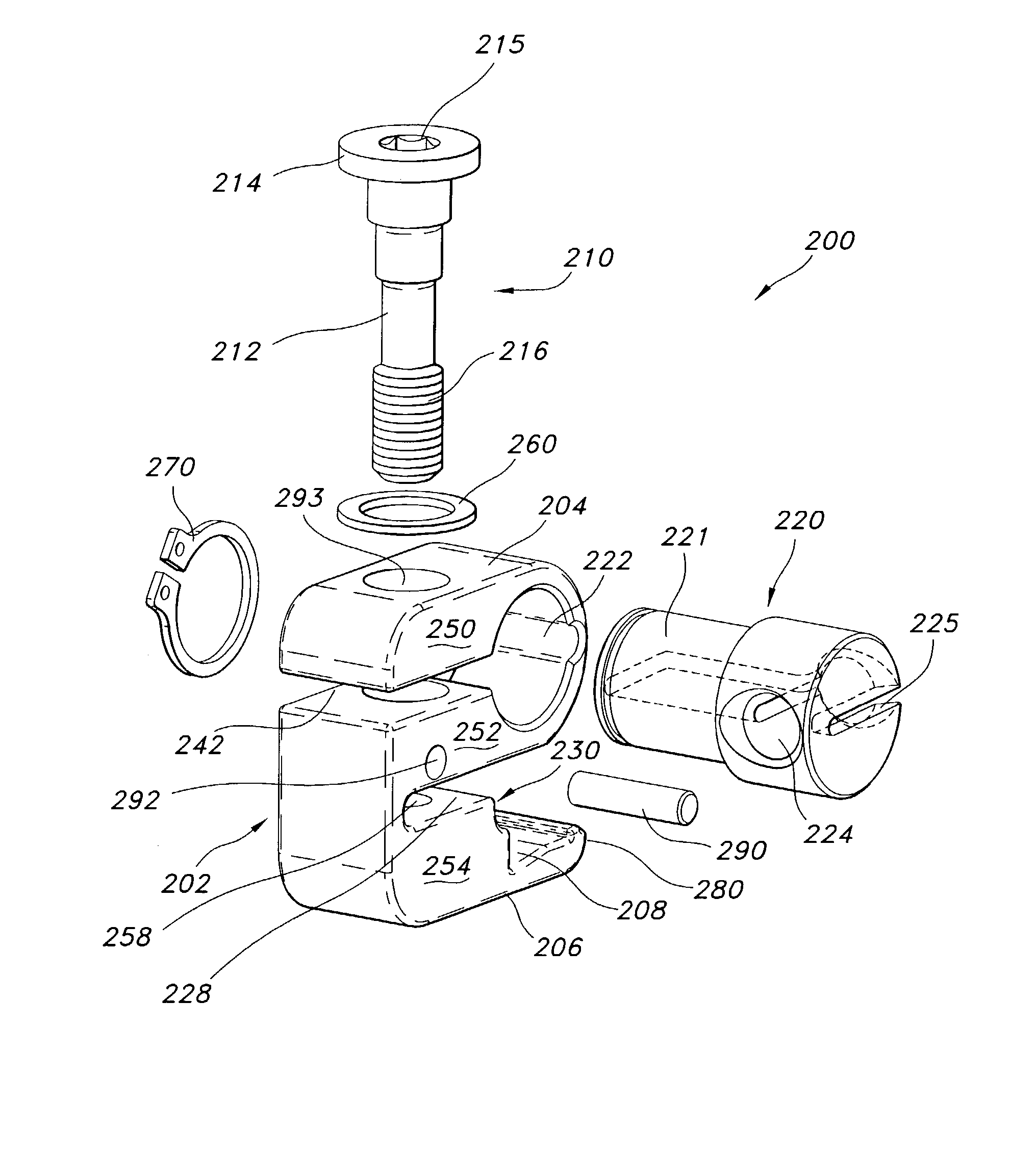
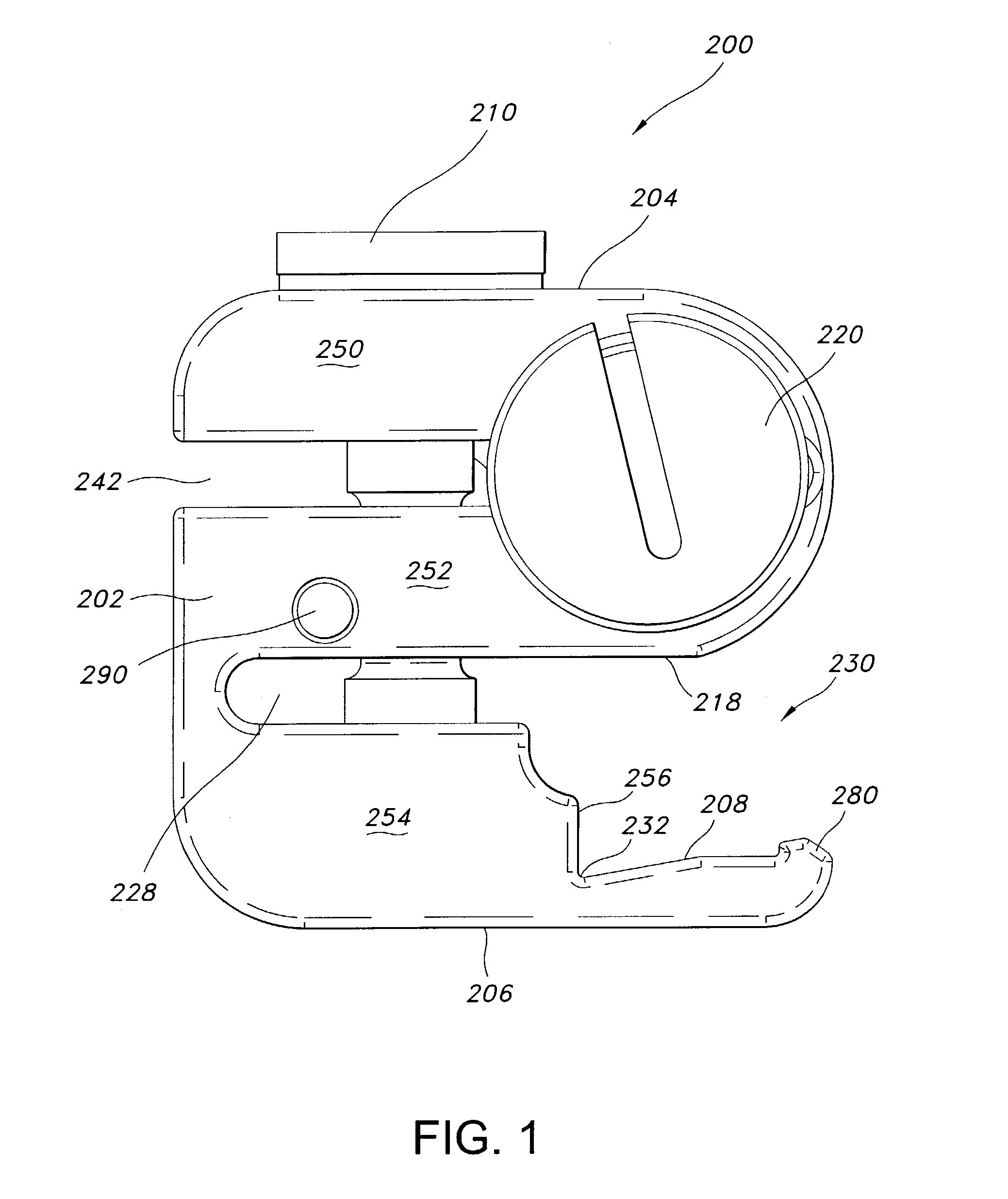
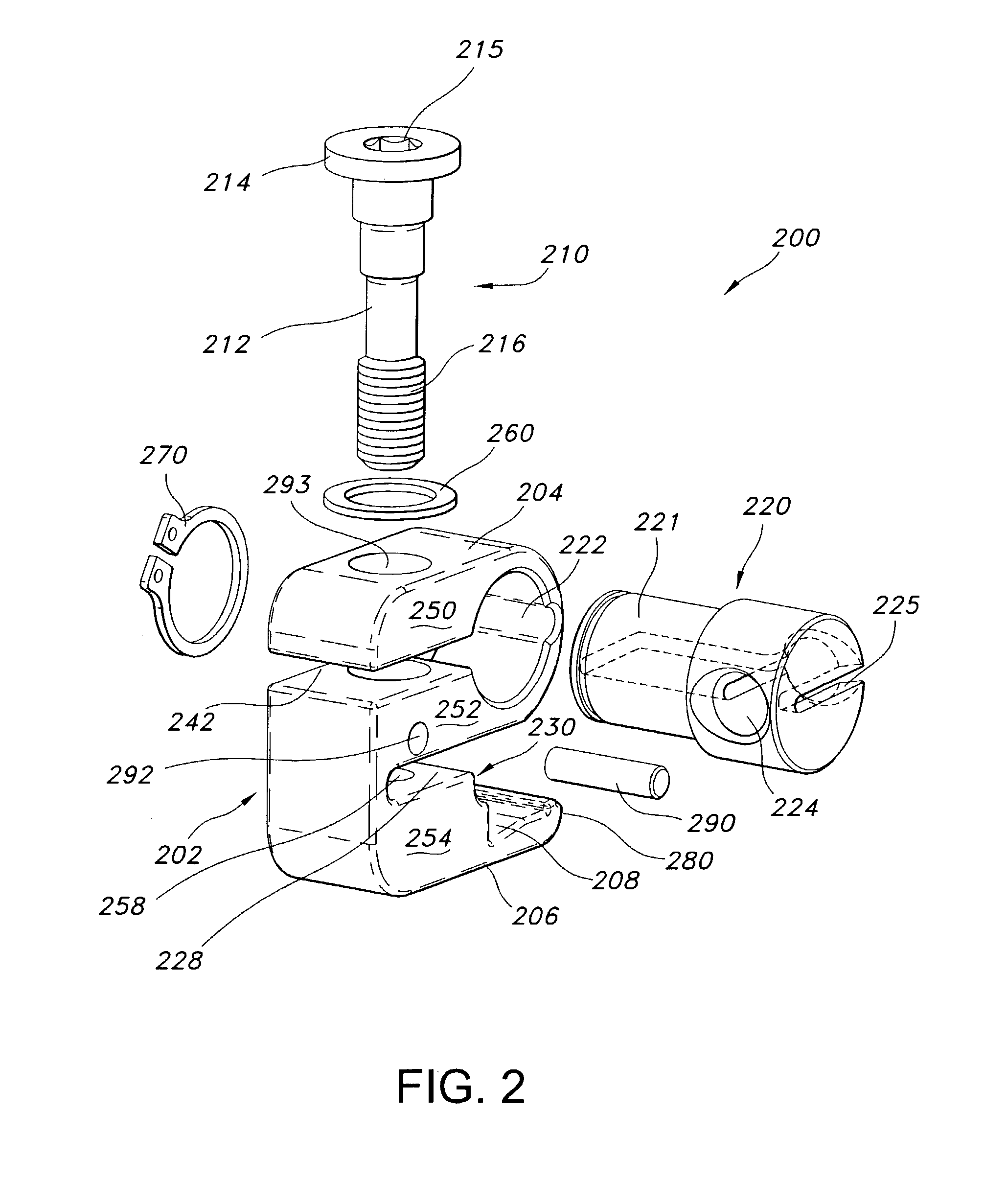
[0012]The methods and apparatus of the invention help to satisfy this need by providing a unique clamp structure that is adapted to help position surgical instruments, such as retractor blades and so forth, in order to expose a surgical site intended to receive an implant. There are numerous ways to desc
Problems solved by technology
Obtaining clear access to a surgical site during any open surgical procedure presents certain challenges.
However, contrary to brain surgery, in most procedures used for spinal surgery, as well as surgery to other body parts, it is difficult to secure an external frame to the patient's skeleton
Method used
Image
Click on the blue label to locate the original text in one second.
Reading with bidirectional positioning of images and text.
Examples
Embodiment Construction
[0035]It will be understood from the description above that the apparatus and techniques of this invention are applicable to a wide variety of procedures, particularly surgical procedures, where precise positioning of an instrument is required. Aspects of the invention are also applicable to any instance in which it is desired to secure any instrument to a support frame or support surface in order to stabilize the instrument with respect to the frame or any reference point relating to the frame.
[0036]The description that follows focuses on one embodiment of the invention—the exposure of the intervertebral space and the implantation of an intervertebral endoprosthesis, and in particular, to the implantation of such an endoprosthesis in the intervertebral space between cervical vertebrae using an anterior approach. Those of ordinary skill in the art will recognize that the procedure described below can be varied or modified to be applicable to other spinal implants such as fusion impl...
PUM
Abstract
The methods and apparatus of this invention provide instrumentation for clamping and securing instruments to support members. Specific embodiments of the invention are particularly useful as devices and methods for use during surgical procedures, such as implantation procedures to properly implant a prosthesis.
Description
[0001]This application is a continuation-in-part of U.S. patent application Ser. No. 09 / 923,891, filed on Aug. 7, 2001, now U.S. Pat. No. 6,949,105, having the title “Improved Method and Apparatus for Stereotactic Implantation,” which is a continuation-in-part of U.S. patent application Ser. No. 09 / 783,860, filed on Feb. 13, 2001 now abandoned, having the title “Method and Apparatus for Stereotactic Implantation,” and a continuation-in-part of U.S. patent application Ser. No. 09 / 783,910, filed on Feb. 13, 2001 now abandoned, having the title “Implantable Joint Prosthesis,” both of which claim benefit under 35, U.S.C. § 119(e) of Provisional U.S. Ser. No. 60 / 223,863, filed Aug. 8, 2000, and entitled “Instrumentation and Method for Implanting a Prosthetic Intervertebral Body” and of Provisional U.S. Ser. No. 60 / 265,218 entitled “Gravity Assisted Localization System,” filed Jan. 31, 2001, all of which are hereby incorporated herein by this reference.FIELD OF THE INVENTION[0002]The inve...
Claims
Application Information
Patent Timeline
Application Date:The date an application was filed.
Publication Date:The date a patent or application was officially published.
First Publication Date:The earliest publication date of a patent with the same application number.
Issue Date:Publication date of the patent grant document.
PCT Entry Date:The Entry date of PCT National Phase.
Estimated Expiry Date:The statutory expiry date of a patent right according to the Patent Law, and it is the longest term of protection that the patent right can achieve without the termination of the patent right due to other reasons(Term extension factor has been taken into account ).
Invalid Date:Actual expiry date is based on effective date or publication date of legal transaction data of invalid patent.
