Method and an apparatus for continuously deaerating a liquid
a liquid and liquid technology, applied in the field of methods and apparatus for continuously deaerating liquids, can solve the problems of deteriorating affecting the efficiency of deaeration, and affecting the quality of products, so as to achieve simple and efficient deaeration and reduce the cos
- Summary
- Abstract
- Description
- Claims
- Application Information
AI Technical Summary
Benefits of technology
Problems solved by technology
Method used
Image

Examples
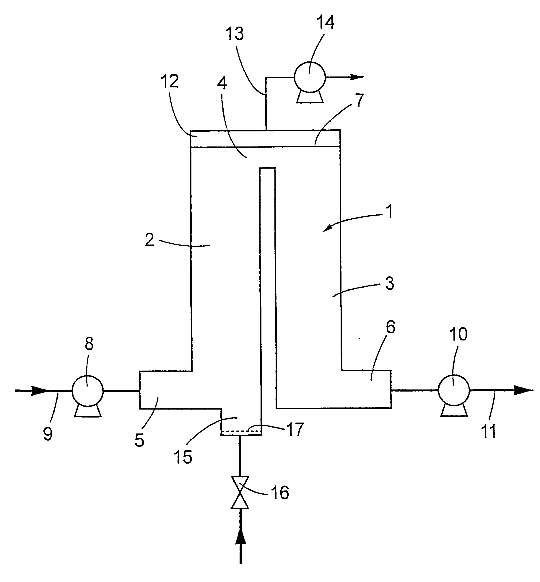
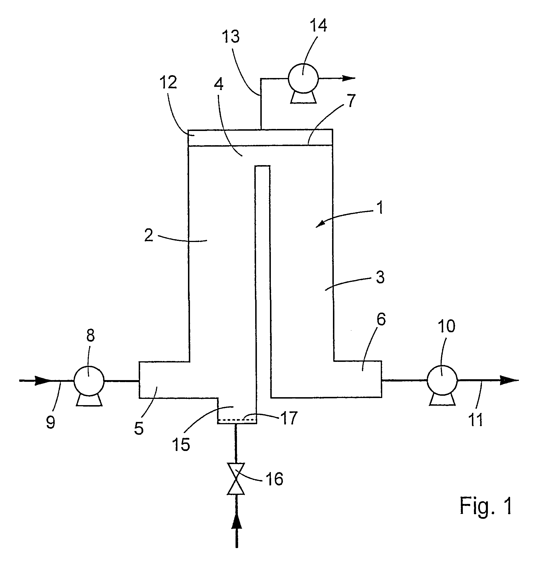
first embodiment
[0030]According to the invention the deaerated liquid is leaving the container 1 via the outlet 6 and is transported further along the conduit 11, possibly helped with the pressurising pump 10.
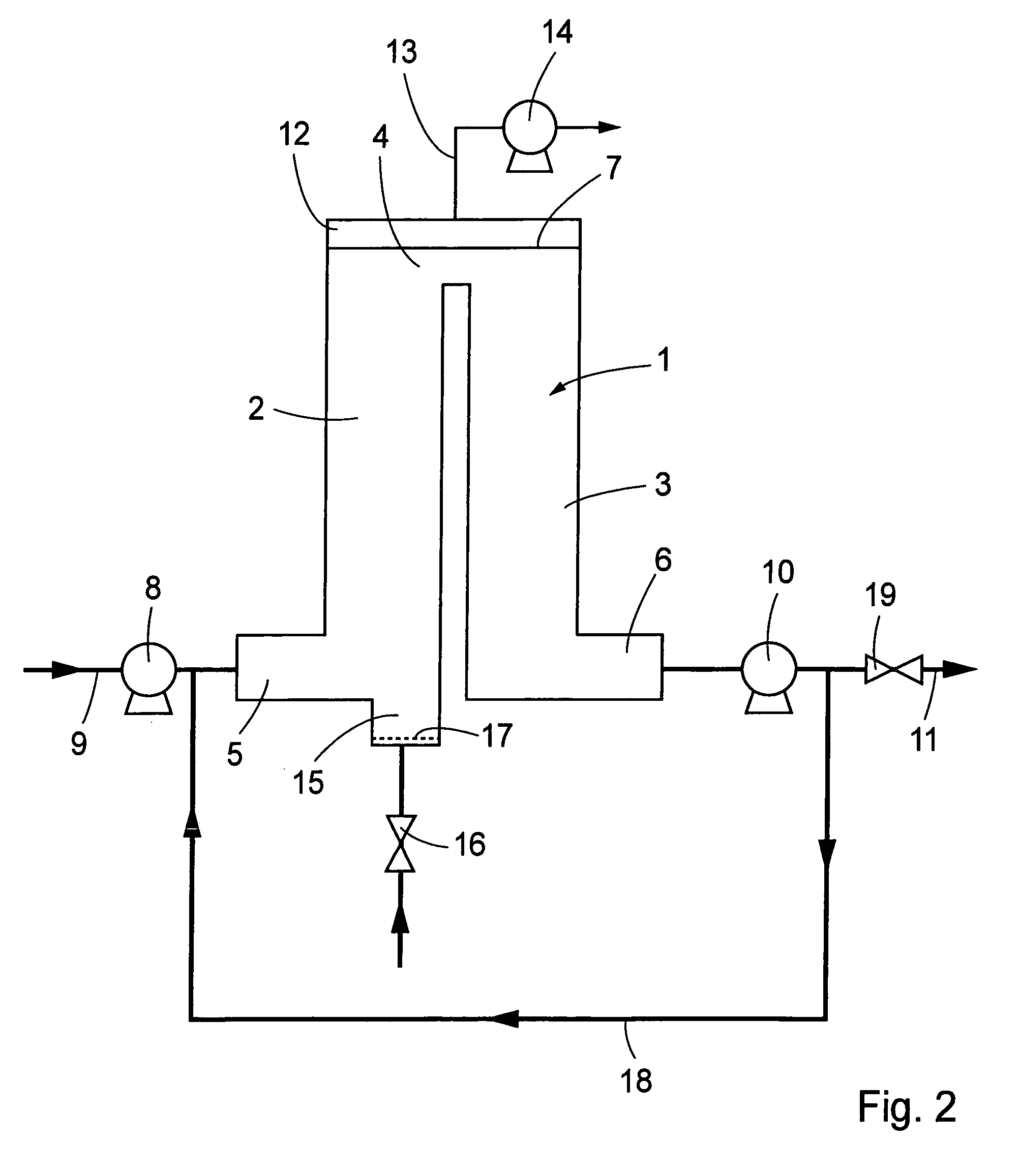
second embodiment
[0031]According to the invention, the liquid leaving the container 1 at the outlet 6 is circulated over the circulation pipe 18, back to the inlet 5 of the container 1. In order to improve the deaeration of the liquid, the liquid is circulated 3 to 5 times over the container 1, before it is transported further along the conduit 11. The container 1 with the inlet 5, the outlet 6, the circulation pipe 18, the pressurising pump 10 and the throttle valve 19 thereby constitute a feed and bleed arrangement.
[0032]The above-described method and the apparatus for carrying the method into effect make for an efficient deaeration which meets those requirements placed by the processing industry for the production of drinks and the like. For example, for juice production, an oxygen content applies of 1 ppm or lower.
[0033]As will have been apparent from the foregoing description, the present invention realises a method for continuously deaerating a liquid which is efficient and economical to carry...
PUM
| Property | Measurement | Unit |
|---|---|---|
| pressure | aaaaa | aaaaa |
| atmospheric pressure | aaaaa | aaaaa |
| temperature | aaaaa | aaaaa |
Abstract
Description
Claims
Application Information