Integrated gradiometer

a magnetic field gradient and integrated sensor technology, applied in the direction of magnetic gradient measurement, magnetic field measurement using galvano-magnetic devices, instruments, etc., can solve the problems of compromising the sensitivity of a gmr element, affecting the accuracy of gmr element detection, etc., to achieve the effect of enabling susceptibility techniques

Inactive Publication Date: 2006-10-24
THE UNITED STATES OF AMERICA AS REPRESENTED BY THE SECRETARY OF THE NAVY
View PDF7 Cites 8 Cited by
  • Summary
  • Abstract
  • Description
  • Claims
  • Application Information

AI Technical Summary

Benefits of technology

[0013]Yet another object of the invention is to provide a two-dimensional array of gradiometer cells for high spatial resolution of objects that have local magnetic fields that vary on a small spatial scale. Integrated readout of the sensors allows rapid readout of the array. A specific application is the recognition of microscopic magnetic particles that have been used to tag an object to be identified.
[0015]The integrated gradiometer, by comparison with simple magnetic field sensors, has numerous advantages. It is ideally suited to the measurement of magnetic fields that vary on a small length scale, and to the discrimination of such fields against larger background fields that are spatially constant (or slowly varying).
[0021]The present invention is optimized for detecting field gradients associated with MPs. It has layer separations of about 1 ′<1 μm, transverse dimensions less than 10 μm, and it is operated at room temperature with the application of an external magnetic field [note—generally we want the range of external field to include zero] and using a comparator readout mode, thus providing performance improvements over alternative devices.
[0023]Also, the present invention unlike the device disclosed in Abulafia et al discussed above is, in a preferred embodiment, a vertical stack of Hall sensors capable of and optimized for detecting field gradients associated with MPs at room temperature. It has layer separations 1′ of 1 μm or less, transverse dimensions less than 10 μm, and is fabricated for operating at room temperature. It includes an astatic geometry for nulling out an external, constant magnetic field, thereby enabling susceptibility techniques.

Problems solved by technology

However, the sensitivity of a GMR element is compromised when the device is fabricated on a small scale because of magnetostatics.
However, the fringing field from a MP that is locally highly non-uniform becomes problematic for several reasons.
First, if the active area of the sensor is much larger than the MP then the magnetoresistance induced from the fringing field is largely shunted out by the unperturbed portion of the sensor.
Furthermore, if the MP is extremely small the highly localized fringing field will be unable to affect a comparably small portion of the sensor.
For many reasons, fabrication of GMR devices become extremely difficult for length scales d less than 1 micron.
These designs do not use sensors that are integrated on a common chip.
These read head gradiometers have not proven to be commercially successful.
It is not capable of measuring the field gradients, that vary on a spatial scale less than 10 microns, associated with magnetic particles because the transverse dimensions are too large.

Method used


Image

  • Integrated gradiometer
  • Integrated gradiometer
  • Integrated gradiometer

Examples


Embodiment Construction

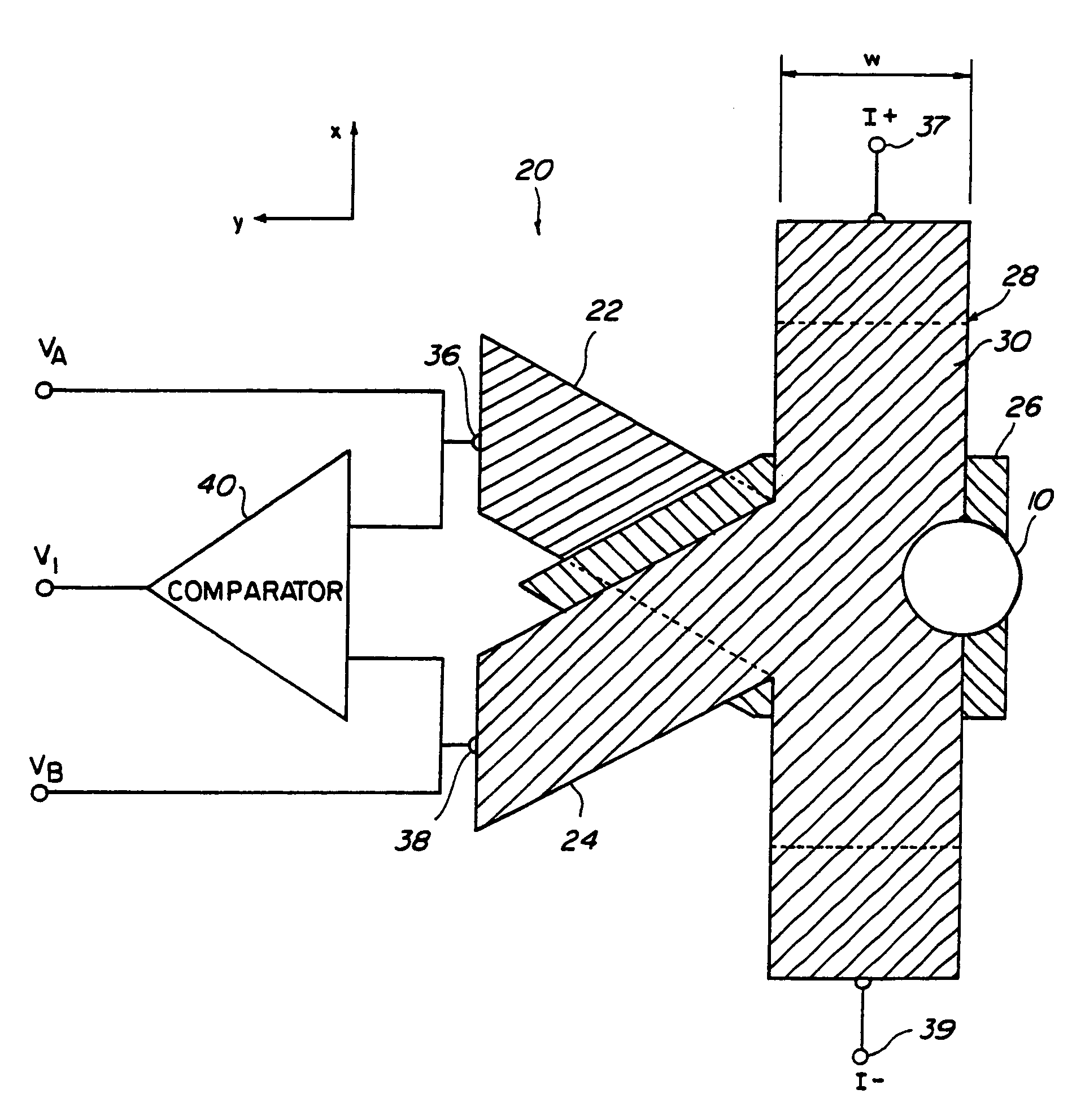
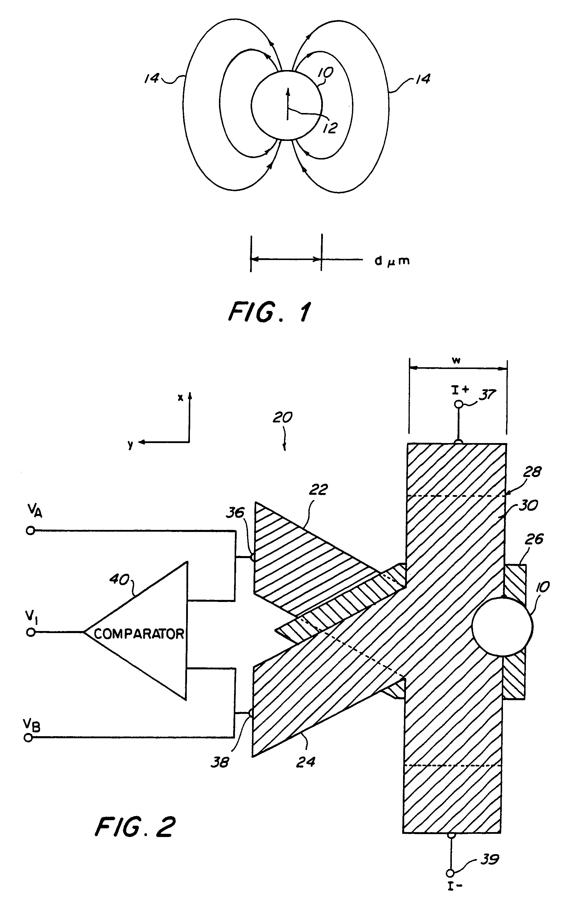
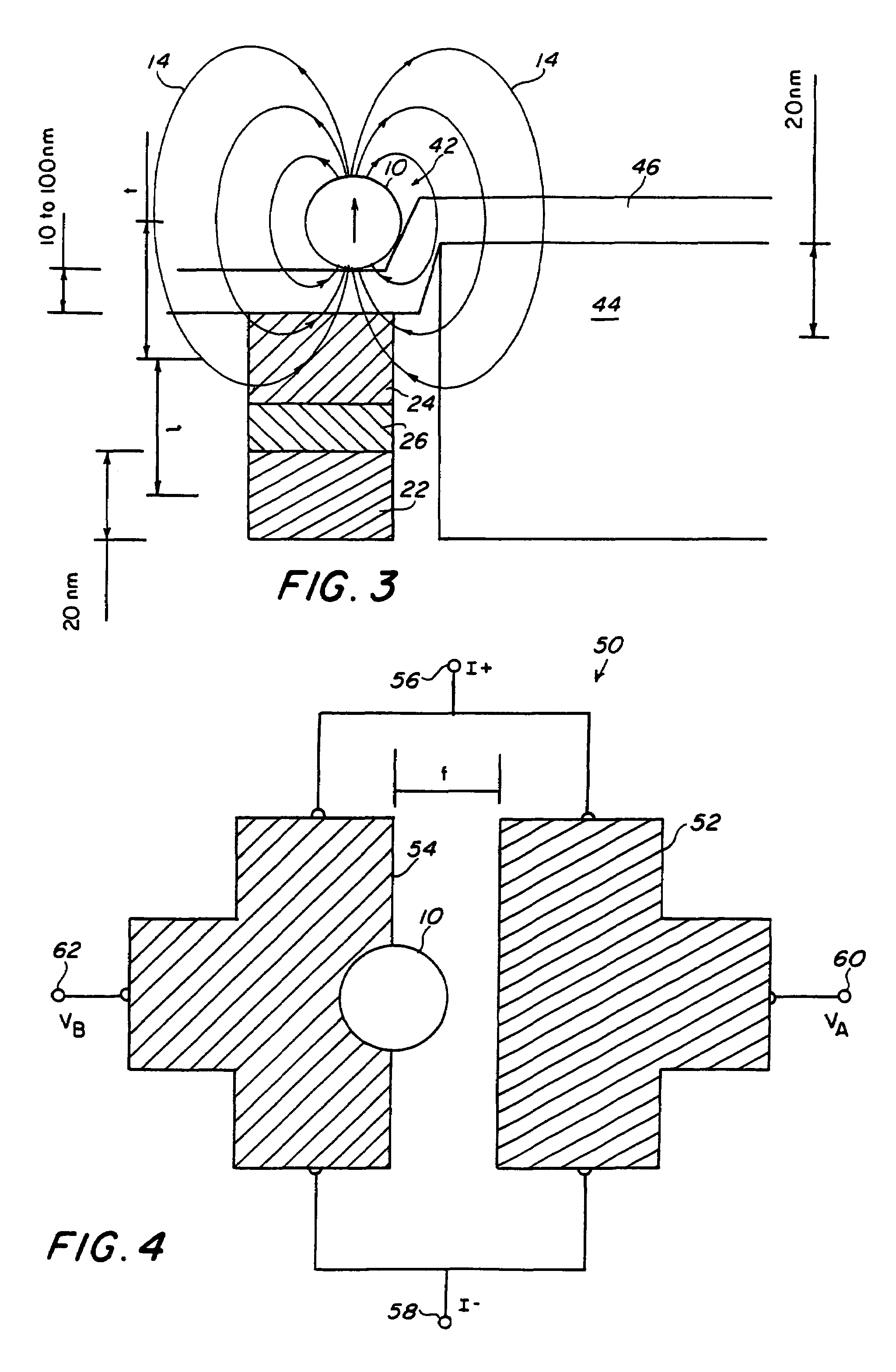
[0031]As used herein, the term “local magnetic field source” refers to a microscopic magnetized object that generates a local magnetic field with an associated field gradient. An example is a microscopic magnetic particle, with diameter of order 10 nm up to 5 microns. Where reference is made herein to first and second sensors that are spaced apart at a distance effective for measuring a magnetic field gradient having a spatial scale of d microns, the meaning is as follows. The locally strong magnetic fields associated with microscopic magnetic particles, or generally any microscopic magnetic structure, can be modeled as coming from a superposition of sources characterized as monopole or dipole. Typically, components from dipolar sources dominate the characteristics of the local field. The spatial scale d that defines the dipole is a characteristic length scale for the spatial variation of the local magnetic field. It has been noted that the lateral dimensions of the first and second...


PUM


Abstract

Magnetic field sensors, each generating an electrical output signal in proportion to the local magnetic field, are lithographically fabricated on a semiconductor substrate with a small spatial separation. The lateral dimension of the sensors and the separation length are the order of the minimum lithographic feature size. Comparing the electrical signals of the sensors results in a measurement of the local magnetic field gradient. Large field gradients, that vary on a small spatial scale, may be associated small magnetic structures such as microscopic magnetic particles. Detection of a field gradient can be used to infer the presence of a magnetic particle.

Description

TECHNICAL FIELD[0001]The present invention relates to an integrated sensor and method for measuring magnetic field gradients. More particularly, the present invention is directed to sensing and measuring magnetic field gradients that spatially vary on a length scale of 10 microns or less, such as are generated by microscopic magnetic particles that may be bound to a target species for identification.BACKGROUND ART[0002]There is an increasing demand for the ability to detect magnetic fields that vary on a small spatial length scale of d μm, where d may vary from the order of 0.01 microns (10 nm) to the order of 10 microns. As one particular example, fields that vary on such a scale are associated with the magnetic moment of magnetic particles (MPs) of diameter d. One method for detecting the presence of such a particle is to sense the accompanying, local magnetic field. These particles, in turn, may be used for a variety of applications, such as “tagging” biological or chemical targe...

Claims


Application Information

Patent Timeline
Patent Type & Authority Patents(United States)
IPC IPC(8): G01R33/07G01R33/02G01R33/022
CPCG01R33/022
Inventor JOHNSON, MARK B.MILLER, MICHAEL
Owner THE UNITED STATES OF AMERICA AS REPRESENTED BY THE SECRETARY OF THE NAVY
Why Eureka
Try Eureka