
Phased null radar

a phased null, radar technology, applied in the field of radar, can solve the problems of limited use of radar systems, interference with such equipment, and the receiver of radars, and achieve the effect of reducing the interference

Inactive Publication Date: 2006-10-24
LOCKHEED MARTIN CORP
View PDF12 Cites 6 Cited by
  • Summary
  • Abstract
  • Description
  • Claims
  • Application Information

AI Technical Summary

Benefits of technology

The invention relates to a method for reducing interference between radar signals. The method involves generating a constant-amplitude pulse with a narrower bandwidth than the radar's actual bandwidth. The pulse is then phase-perturbed to produce a new pulse with reduced amplitude in the other radar's bandwidth. This new pulse is transmitted towards a target to reduce interference with the other radar's signals. The method can also be used to reduce interference between long-range and short-range radar signals by selectively applying phase perturbations to one of the signals. The technical effect of this invention is to improve the accuracy and reliability of radar systems by reducing interference and improving signal-to-noise ratios.

Problems solved by technology

These energy components may interfere with such equipments occupying other frequency sub-bands away from the bandwidth of the radar.
In times past, the interference was usually manifested in non-radar equipment in these other frequency ranges or sub-bands, because of the relatively high power of the radar pulses, although some interference with the radar receiver by other equipments occasionally occurred.
The broad bandwidth and high power of radar pulses still causes interference in equipments operating in nearby frequency bands, but there are now many more such equipments than in the past.
In extreme cases, a radar system may be limited to use only in wartime.
Even if operation of a radar in peacetime is allowed, the paucity of available operating bandwidth and its effect on frequency diversity may compromise system performance.

Method used


Image

  • Phased null radar
  • Phased null radar
  • Phased null radar

Examples


Embodiment Construction

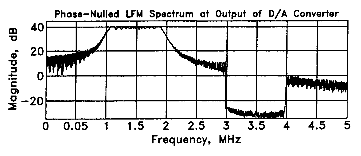
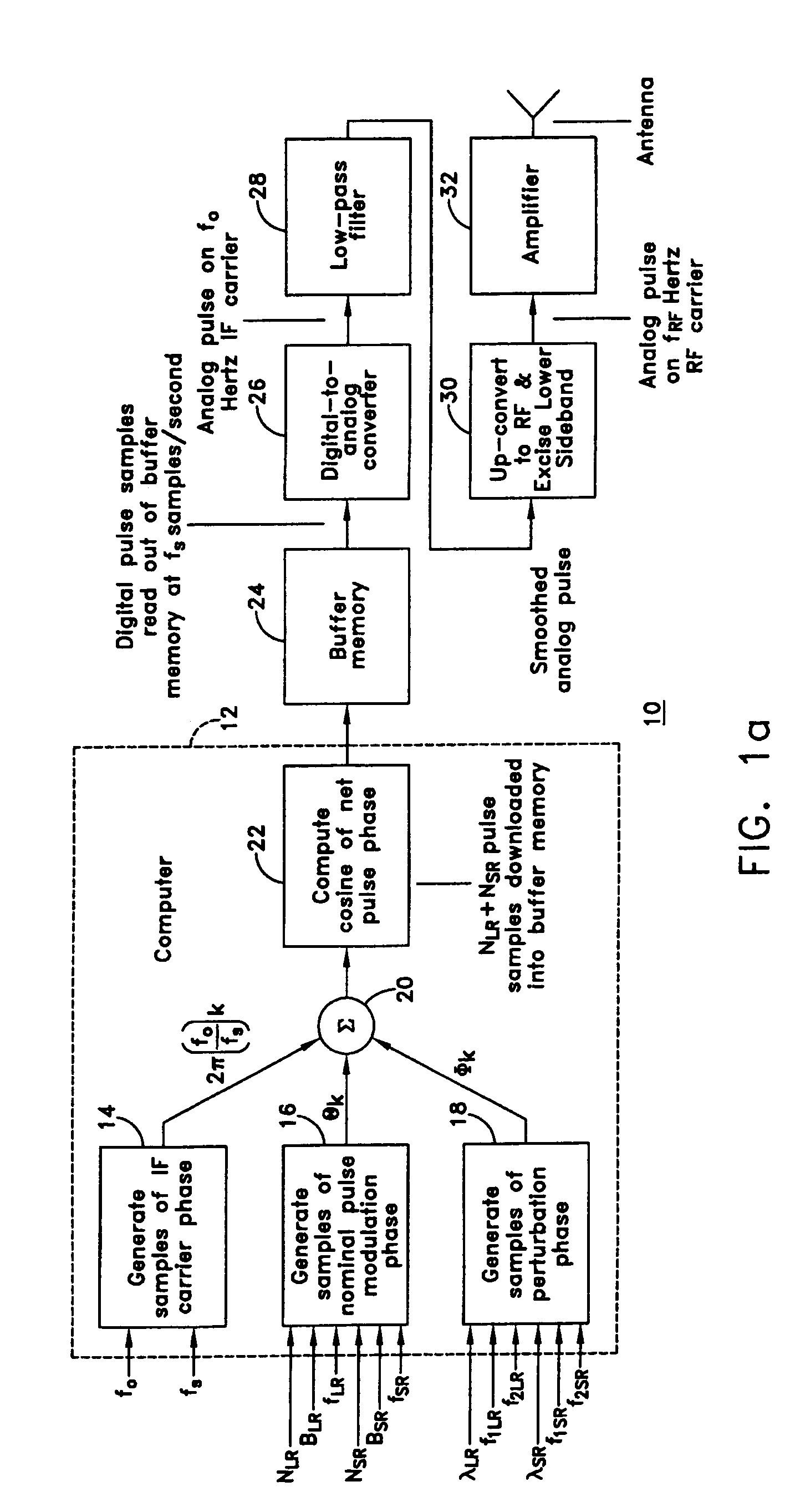
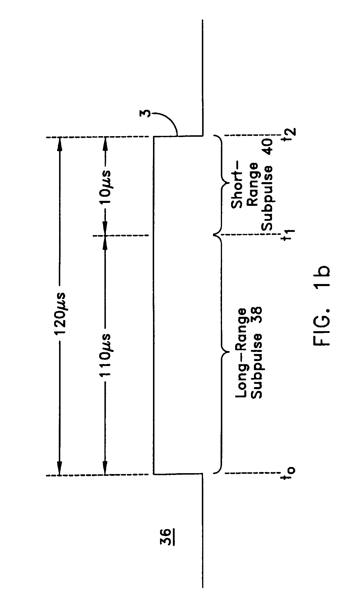
[0026]In FIG. 1a, a portion 10 of a radar transmitter uses a computer 12 including a portion 14 to generate digital phase samples at a sample rate fs of constant-amplitude pulse with arbitrary intermediate frequency (IF) carrier frequency f0. The output signal of block 14 may be represented as 2π(f0 / fs)k, where k is the sample index, 0≦k≦(NLR+NSR−1) A portion 16 of computer 12 produces a nominal but arbitrary phase modulation function Θ from input information including NLR, NSR, the number of samples in the long- and short-range subpulses, respectively; BLR, BSR, the bandwidths of the long- and short-range pulses, respectively; and fLR, fSR, the center frequencies of the long- and short-range subpulses, respectively. The output signal of block 16 is designated Θk. Furthermore, computer 12 includes a generator 18 for a phase perturbation function Ø to exert fine control over the spectral response of the pulse, based on input information λLR, λSR, the null depth parameters for the lon...


PUM


Abstract

A method for reducing the interference between a source transmitting pulses and equipments having nominal bandwidths which are outside the nominal bandwidth of the transmitted pulses, but which respond to sideband energy of the pulses. Phase perturbations are applied to the edges of the pulses produced by the source, to thereby tend to null the sideband energy lying in the nominal bandwidth of the equipments occupying the adjacent nominal bandwidths.

Description

FIELD OF THE INVENTION[0001]This invention relates to radar, and more particularly to radar that transmits constant-amplitude broadband pulses, and especially to reduction of out-of-sub-band components lying in another sub-band.BACKGROUND OF THE INVENTION[0002]Radar systems traditionally transmit electromagnetic pulses at a nominal center frequency toward the region in which targets are expected to be found, and detect the presence of the target by receiving reflected pulses during the inter-transmit-pulse interval. It has long been known that these transmitted pulses have an overall bandwidth which is a function of the pulse width, and which can be affected by the rise and fall times of the pulses, as well as the width and shape of the pulse envelope (including amplitude modulation and the shape of the leading and trailing edges), and the pulse's phase (including frequency) modulation. The bandwidth of high-power electromagnetic pulses with rapid rise and fall times is such that si...

Claims


Application Information

Patent Timeline
Patent Type & Authority Patents(United States)
IPC IPC(8): G01S13/00G01SG01S7/282G01S13/02G01S13/28
CPCG01S7/023G01S7/282G01S13/288G01S7/0233
Inventor WASIEWICZ, RICHARD
Owner LOCKHEED MARTIN CORP
Learn More