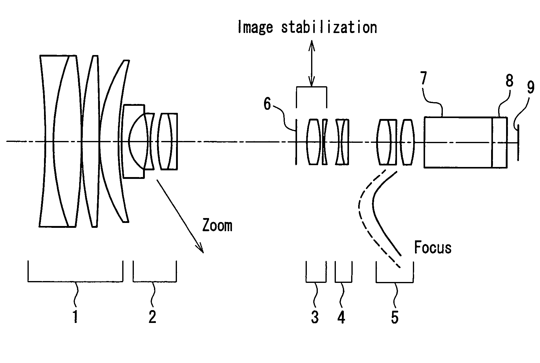
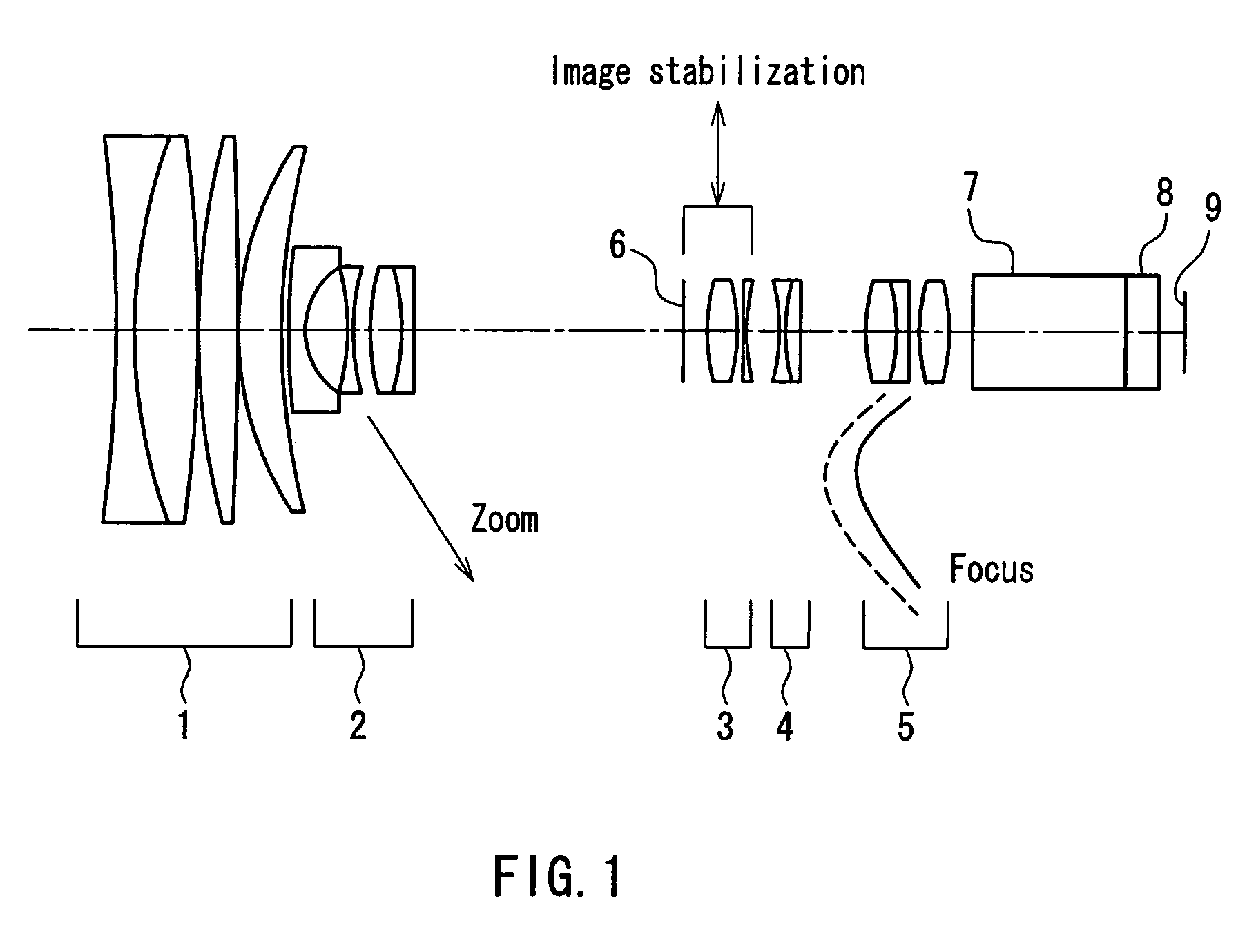
Image stabilizing zoom lens
a zoom lens and image stabilization technology, applied in the field of highmagnification ratio and highimage quality zoom lenses, can solve the problems of increasing the load on the driving system, reducing the zoom ratio, and reducing the size of the lens, so as to achieve the effect of sufficient zoom ratio
- Summary
- Abstract
- Description
- Claims
- Application Information
AI Technical Summary
Benefits of technology
Problems solved by technology
Method used
Image
Examples
example 1
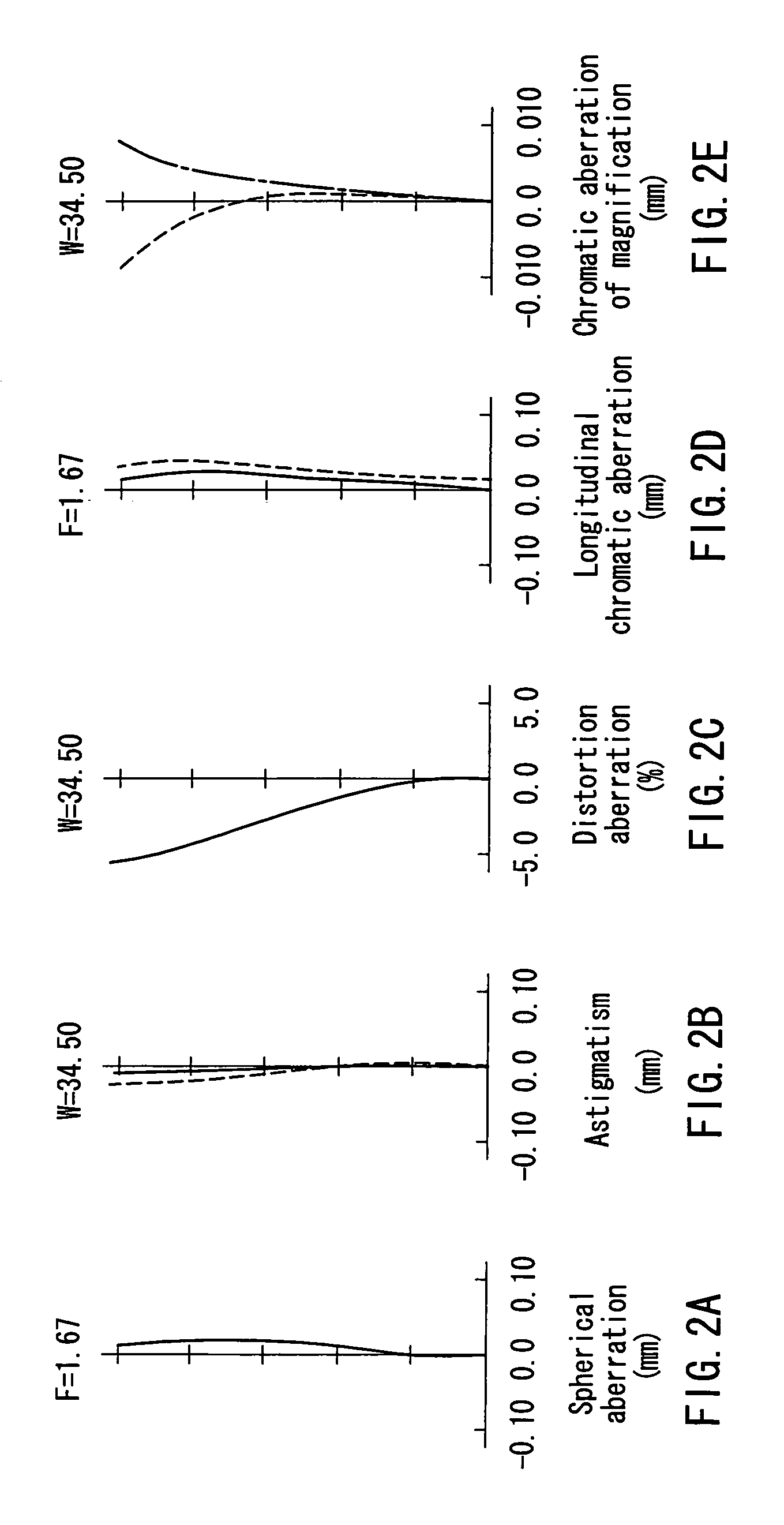
[0065]Table 1 shows a numerical example of a zoom lens according to Example 1. It should be noted that in Table 1, r denotes the radius of curvature of the lens faces, d denotes the lens thickness or the air interval between the lenses, n denotes the refractive index of the lenses at the d-line, and v denotes the Abbe number of the lenses at the d-line. Moreover, the aspherical coefficients for this example are listed in Table 2.
[0066]Here, aspherical surfaces are given by the following equation:
[0067]SAG=H2 / R1+1-(1+K)(H / R)2+D·H4+E·H6+F·H8
[0068]SAG: distance of the point on the aspherical surface from the vertex of the aspherical surface at the height H from the optical axis
[0069]H: height from the optical axis
[0070]R: radius of curvature at the vertex of the aspherical surface
[0071]K: conical constant
[0072]D, E, F: aspherical coefficients.
[0073]Moreover, for the air intervals that are variable by zooming, Table 3 lists values when the object point is at infinity. In Table 3, the s...
example 2
[0081]Table 4 shows a numerical example of a zoom lens according to Example 2, and the aspherical coefficients for this case are listed in Table 5. Moreover, for the air intervals that are variable by zooming, Table 6 lists values for when the object point is at infinity.
[0082]
TABLE 4unitsurfacerdnv11−325.7742.501.8466523.8268.9937.851.4969981.63−149.0750.20491.8464.701.8060040.75−715.5340.20641.9165.301.8349942.77109.233var.28109.2331.001.8349942.799.8326.0010−22.6901.351.6060257.41122.6901.351225.8183.601.8466523.813−25.8181.001.8340137.214∞var.aperture15—2.50——stop31624.7023.001.5145063.117−24.7020.8018∞1.051.8051825.41960.0003.50420−23.1271.001.6968055.62123.1271.801.8466523.822∞var.52328.3983.001.4874970.424−28.3981.001.8466523.82554.7501.002614.9614.501.5145063.127−14.961var.628∞20.001.5891361.229∞3.001.5163364.130∞—
[0083]
TABLE 5surfaceKDEF101.19362E+003.38265E−051.29210E−07−5.83703E−10111.19362E+00−3.38265E−05−1.29210E−075.83703E−1016−1.32081E−01−1.36623E−05−1.84002E−080.0000...
example 3
[0088]Table 7 shows a numerical example of a zoom lens according to Example 3, and the aspherical coefficients for this case are listed in Table 8. Moreover, for the air intervals that are variable by zooming, Table 9 lists values for when the object point is at infinity.
[0089]
TABLE 7unitsurfacerdnv11350.0002.501.8466523.8249.9587.751.4969981.63∞0.20471.3664.901.8060040.75700.0000.20644.1495.301.8349942.77135.024var.28135.0241.001.8349942.7910.1416.0010−21.3511.351.6060257.41121.3511.351226.1423.601.8466523.813−26.1421.001.8340137.214∞var.aperture15—2.50——stop31624.3063.001.5145063.117−24.3060.8018∞1.051.8051825.41960.0003.50420−23.0881.001.6968055.62123.0881.801.8466523.822∞var.52328.1853.001.4969981.624−28.1851.001.8466523.82555.1571.002615.0584.501.6060257.427−15.058var.628∞20.001.5891361.229∞3.001.5163364.130∞—
[0090]
TABLE 8surfaceKDEF101.83153E−012.40673E−056.75939E−08−8.81965E−10111.83153E−01−2.40673E−05−6.75939E−088.81965E−1016−1.81885E−01−1.41053E−05−1.37944E−080.00000E+0017−...
PUM
 Abstract
Description
Claims
Application Information
 - R&D
- Intellectual Property
- Life Sciences
- Materials
- Tech Scout
- Unparalleled Data Quality
- Higher Quality Content
- 60% Fewer Hallucinations
Browse by: Latest US Patents, China's latest patents, Technical Efficacy Thesaurus, Application Domain, Technology Topic, Popular Technical Reports.
© 2025 PatSnap. All rights reserved.Legal|Privacy policy|Modern Slavery Act Transparency Statement|Sitemap|About US| Contact US: help@patsnap.com


