Fluid machine, wind turbine, and method for increasing velocity of internal flow of fluid machine, utilizing unsteady flow

a fluid machine and wind turbine technology, applied in the direction of electric generator control, other chemical processes, final product manufacturing, etc., can solve the problems of converting approximately 40% of the kinetic energy of the wind flowing inside the wind turbine into electric power, the conventional wind turbine has no clue about how to solve this problem, and the rotation of the wind turbine is often misidentified, etc., to achieve design and production easy, increase the velocity of internal flow, and increase the effect of siz

Inactive Publication Date: 2012-04-12
KYUSHU UNIV
View PDF5 Cites 14 Cited by
  • Summary
  • Abstract
  • Description
  • Claims
  • Application Information

AI Technical Summary

Benefits of technology

[0026]According to the fluid machine utilizing an unsteady flow of the present invention, a casing can be designed and produced easily, and by virtue of the shape of the casing, a strong and stable vortex street flow is formed in the flow, a strong negative pressure region is made in the vicinity of the casing on the outlet side thereof, and the velocity of an internal flow is increased, the size can be made larger with a short flow passage, and high output power generation can be performed.
[0022]Furthermore, another object of the present invention is to provide a wind turbine according to which a casing can be designed and produced easily, and by virtue of the shape of the casing, a strong and stable vortex street flow is formed in the outside wind, a strong negative pressure region is made in the vicinity of the casing on the outlet side thereof, the velocity of influent wind is increased, the size can be made larger with a short flow passage, and high output power generation can be performed.
[0028]According to the method for increasing the velocity of the internal flow of a fluid machine of the present invention, a casing can be designed and produced easily, and by virtue of the shape of the casing, a strong and stable vortex street flow is formed in the flow, a strong negative pressure region is made in the vicinity of the casing on the outlet side thereof, and the velocity of the internal flow is increased.

Problems solved by technology

However, a wind power generation apparatus, even a large wind turbine regarded to have high efficiency, can only convert approximately 40% of the kinetic energy of the wind flowing inside the wind turbine into electric power.
However, most of conventional wind turbines have an impeller exposed in the atmosphere, and there are many wind turbines installed in the peripheries of airports, for example.
In the periphery of such an airport, an aviation Doppler radar is installed to monitor the movements of airplanes; however, the rotation of the wind turbines is frequently misidentified as the approach or taking off of small airplanes.
This is recognized as a serious problem in regional airports in Europe and America, where many wind turbines are used in particular.
However, a clue about how to solve this problem has not been found in the conventional wind turbines.
As a problem similar to this, there is a problem of bird strikes.

Method used


Image

  • Fluid machine, wind turbine, and method for increasing velocity of internal flow of fluid machine, utilizing unsteady flow
  • Fluid machine, wind turbine, and method for increasing velocity of internal flow of fluid machine, utilizing unsteady flow
  • Fluid machine, wind turbine, and method for increasing velocity of internal flow of fluid machine, utilizing unsteady flow

Examples


embodiment 1

[0082]Hereinafter, a fluid machine, more particularly a wind turbine, and a method for increasing the velocity of the internal flow of the fluid machine utilizing an unsteady flow, according to Embodiment 1 of the present invention will be described. However, it is basically applicable to other fluid machines, such a hydraulic turbine.

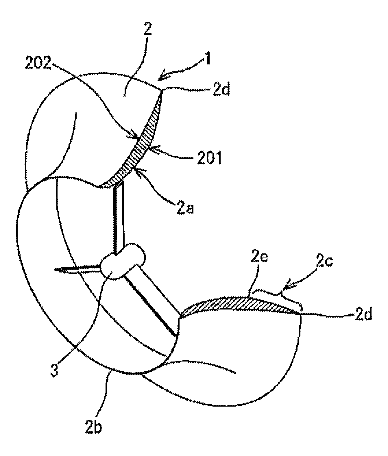
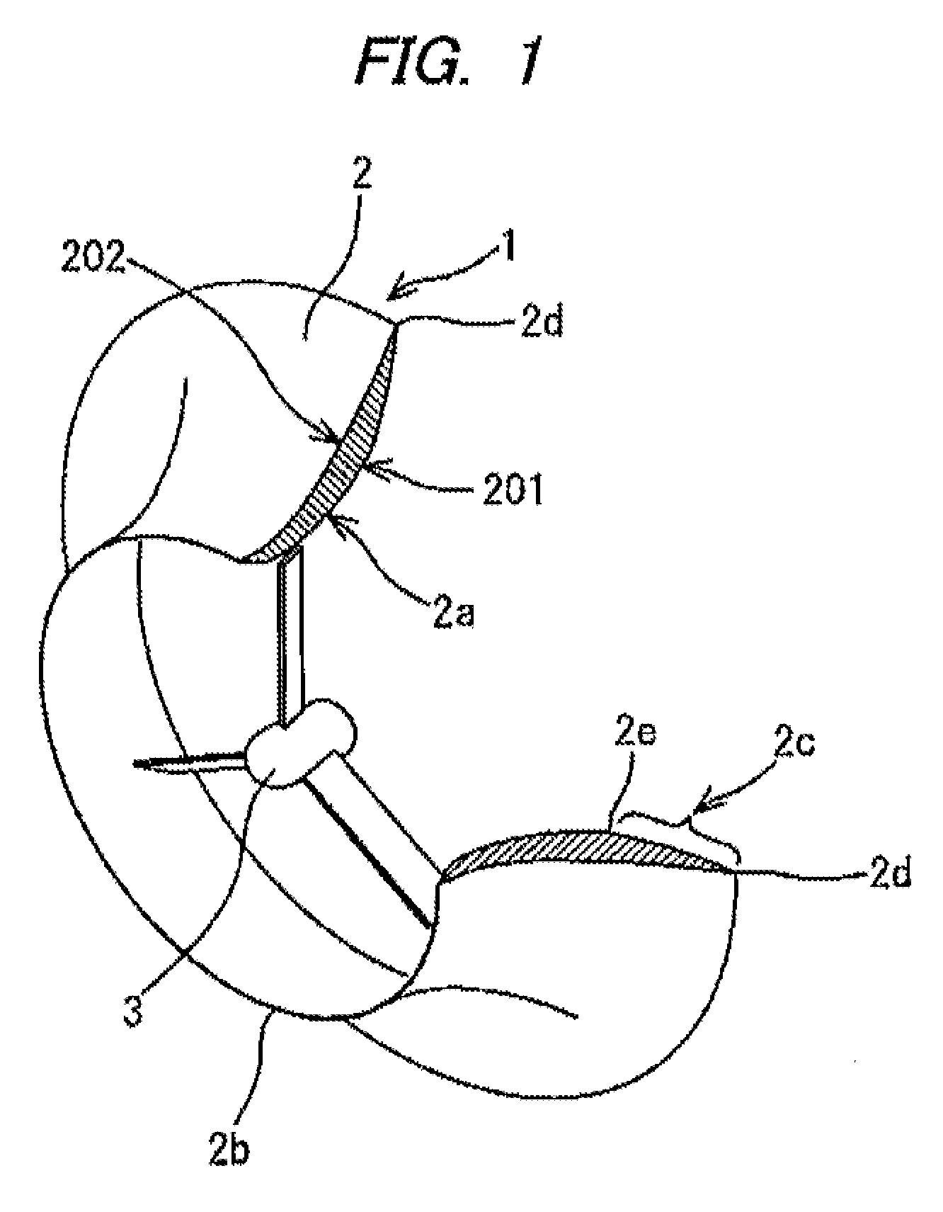
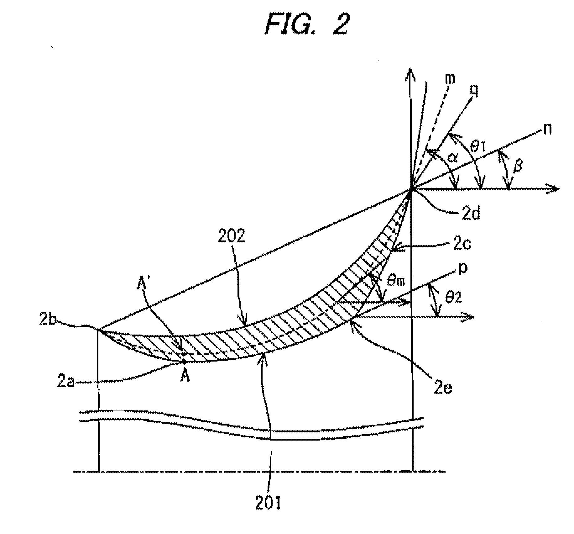
[0083]FIG. 1 is a partly broken-away perspective view showing a fluid machine according to Embodiment 1 of the present invention, FIG. 2 is an axial-direction sectional view showing a casing having a thickness and basically formed into a cycloid curve and provided between the front edge and the rear edge of the fluid machine according to Embodiment 1 of the present invention, and FIG. 3 is an explanatory view illustrating the flow around the fluid machine shown in FIG. 1.

[0084]As shown in FIGS. 1, 2 and 30, the fluid machine according to Embodiment 1 of the present invention is a wind turbine 1, and a power generator for power generation is connected t...

embodiment 2

[0128]According to Embodiment 2 of the present invention the casing of a fluid machine or a wind turbine described above is formed of a plate having a predetermined thickness in the radial direction, and the shape itself on the inner circumferential side including the vortex generating face is formed of a cycloid curve. Hence, it is basically the same as Embodiment 1. FIG. 11 is an axial sectional view showing a casing made of a plate, formed into a cycloid curve and provided between the front edge and the rear edge of a fluid machine according to Embodiment 2 of the present invention. Although a wind turbine is also described mainly in Embodiment 2, the description is similarly applicable to other fluid machines, such as a water turbine.

[0129]As shown in FIG. 11, a plate having a predetermined thickness Δ can be formed into a cycloid shape. Although the casing having a cycloid shape has already been described, the inner circumferential face 201 is formed into a cycloid shape using ...

embodiment 3

[0147]Next, according to Embodiment 3 of the present, the thickness of the casing of the fluid machine is changed, and a flange-shaped vortex generating face is formed. The face has a shape of a thick cut end cross-section, the thickness of which is increased gradually and decreased suddenly. FIGS. 16(a) and 16(b) are comparison views in which the shape of a flanged casing having a flange height of 10% and a tube length of 22% is compared with the shape of a casing having the thick out end cross-section according to Embodiment 3, and FIG. 17 is an axial sectional view showing the thick cut end casing provided between the front edge and the rear edge of the fluid machine according to Embodiment 3 of the present invention. Hereafter, the shape being made thicker gradually and having the thick cut end cross-section (hereafter also referred to as a banana-shaped cross-section) for forming the flange-shaped vortex generating face at the rear edge will be described.

[0148]FIGS. 16(a) and 1...


PUM


Abstract

A fluid machine, a wind turbine, and a method for increasing velocity of an internal flow is provided. A basic shape of the casing has a cycloid curve having a convex portion at a throat section between the front and rear edges. The throat section and a vortex generating face disposed downstream of the throat section to generate the negative pressure region are formed on an inner circumferential face of the casing. A first outflow gradient is formed on an outer circumferential face of the casing and at the rear edge. A second outflow gradient is formed on a boundary of a throat-side adjacent face adjacent to the vortex generating portion to separate the internal flow. The negative pressure region of high vorticity is generated behind the vortex generating face by virtue of the non-streamline shaped casing to increase the velocity of the internal flow.

Description

TECHNICAL FIELD[0001]The present invention relates to a fluid machine operated with internal and external flows and utilizing an unsteady flow, a wind turbine which carries out high output power generation by increasing the velocity of the internal flow caused by wind in the atmosphere, and a method for increasing the velocity of the internal flow of the fluid machine.BACKGROUND ART[0002]In recent years, global-scale environmental issues including global warming or energy issues including the start of the depletion of energy resources, such as oil, which were once believed inexhaustible are being recognized worldwide.[0003]Under these circumstances, wind power generation not emitting CO2 is attracting lots of attention as energy producing means for resolving both the environmental and energy issues. However, a wind power generation apparatus, even a large wind turbine regarded to have high efficiency, can only convert approximately 40% of the kinetic energy of the wind flowing insid...

Claims


Application Information

Patent Timeline
Patent Type & Authority Applications(United States)
IPC IPC(8): F03D9/00F01D25/24F03D1/04
CPCF03B13/264F03D1/04F05B2240/122F05B2240/133Y10S416/02Y02E10/28Y02E10/721Y10S415/908F05B2260/99F03D9/25Y02E10/30Y02E10/72Y02P70/50Y02E10/20
Inventor OHYA, YUJIKARASUDANI, TAKASHIWATANABE, KIMIHIKO
Owner KYUSHU UNIV
Why Eureka
Try Eureka