Lifting device for visual screens

a technology for visual displays and lifting devices, which is applied in the direction of variable height tables, office tables, cabinets, etc., can solve the problems of not providing enough stability to support the weight of a lift and the display, and achieve the effect of reducing the chance of injury and ensuring safety of construction

Inactive Publication Date: 2006-10-31
OKNINSKI MAREK
View PDF14 Cites 46 Cited by
  • Summary
  • Abstract
  • Description
  • Claims
  • Application Information

AI Technical Summary

Benefits of technology

[0008]According to an exemplary embodiment, all working parts are fully housed inside the lift's enclosure and not accessible by user. It is further contemplated that the lift doesn't have any horizontally placed parts, which could create a cutting action. These features dramatically decrease the chance of injury by a user or child, while the lift is in action, making the present invention a much safer construction than prior lifts, which did not offer a way of enclosing all working parts.

Problems solved by technology

This is done because in many cases, the back of the furniture is made out of ¼″ thick MDF or Flake Board, for example, which doesn't provide enough stability to support the weight of a lift and the display.

Method used


Image

  • Lifting device for visual screens
  • Lifting device for visual screens
  • Lifting device for visual screens

Examples


Embodiment Construction

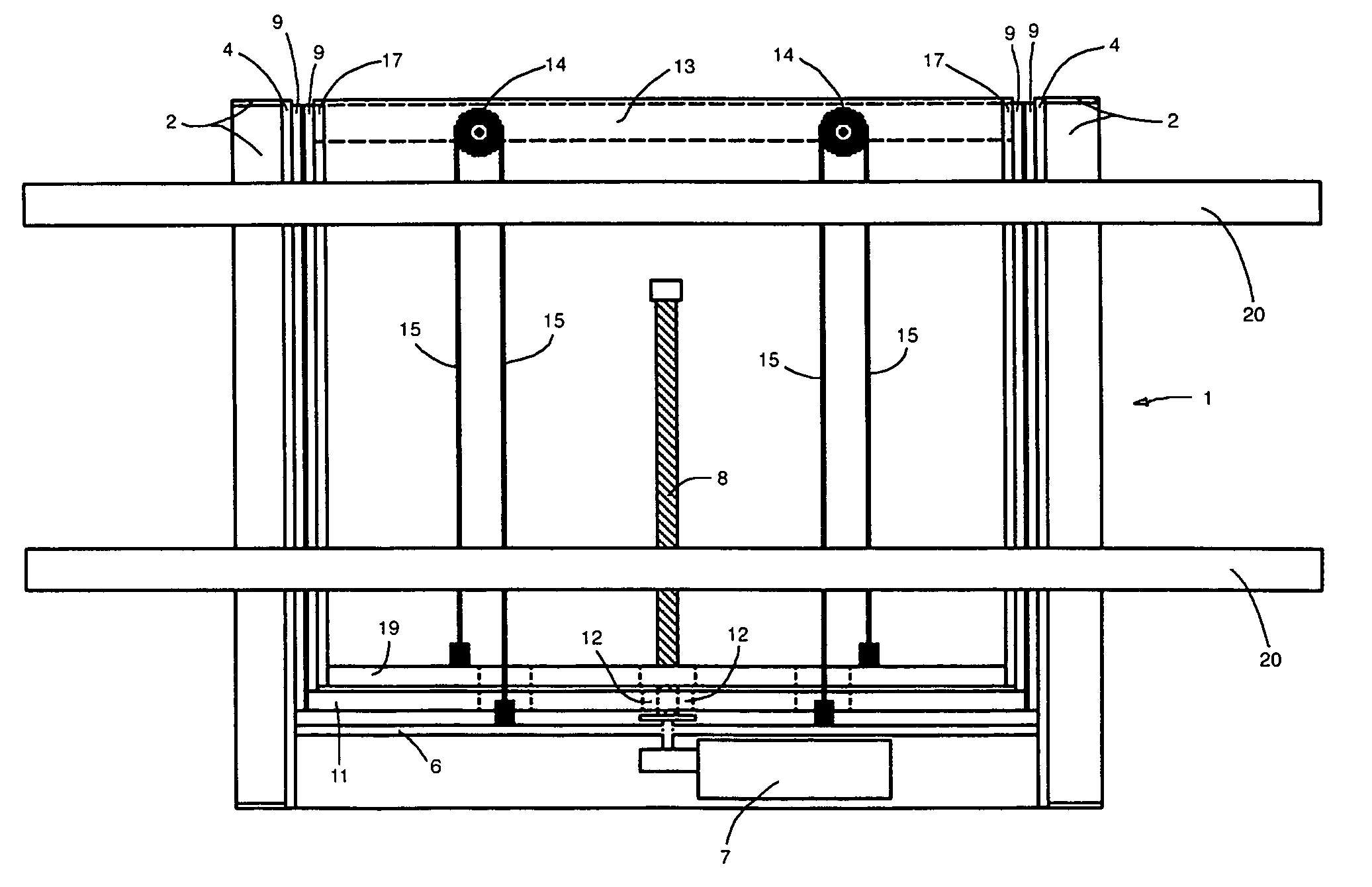
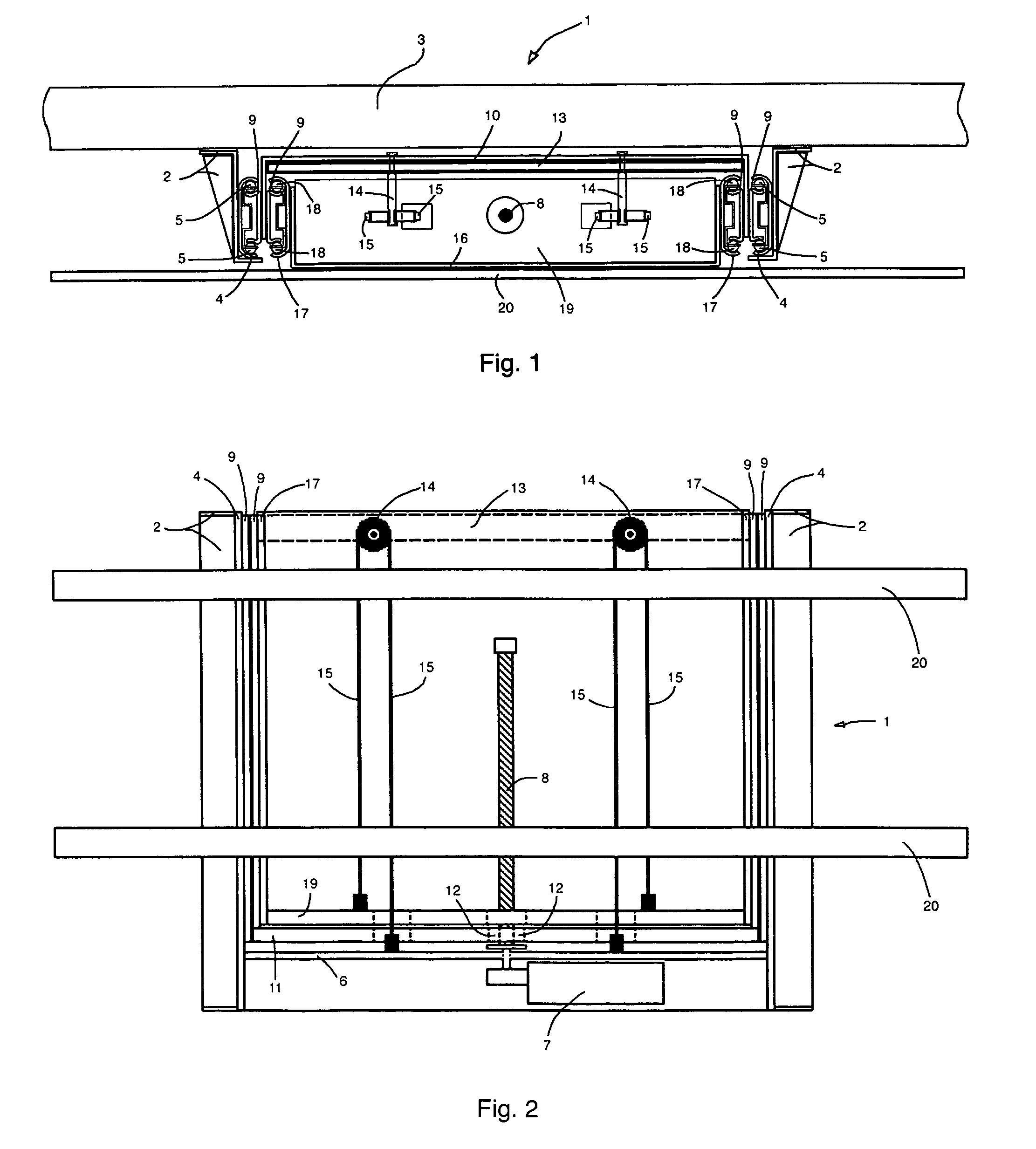
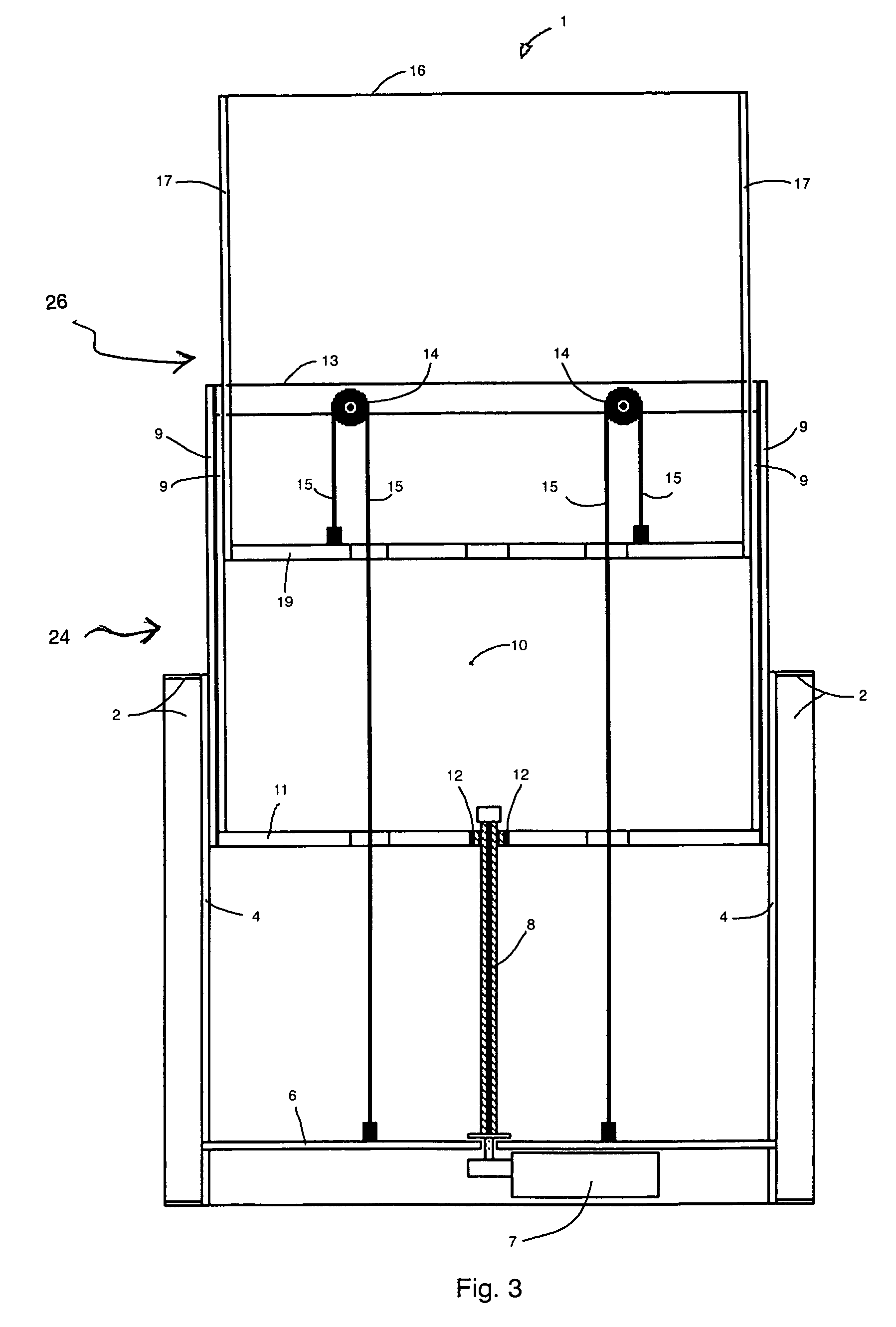
[0014]Referring now to the FIGS. 1–3, an elevating apparatus 1 is shown having a pair of lift-mounting brackets 2 mounted to a mounting panel 3, and a pair of outer slide members 4 attached to the lift-mounting brackets 2. A horizontal motor-mount bar 6 is attached to the lift-mounting brackets 2, and a single shaft right angle gear motor 7 is mounted to the motor-mount bar 6. A single vertical threaded rod 8 is mounted to a shaft of gear motor 7. Two pairs of inner slide members 9 are attached to a back panel 10. Ball bearings 5 are disposed between the inner slide members 9 and the lift-mounting brackets 2. A horizontal bar 11 is attached to the back panel 10. A single threaded nut 12 is mounted on the vertical threaded rod 8 and attached to the horizontal bar 11. A sprockets / pulleys-bar 13 is attached to the back panel 10. A pair of sprockets / pulleys 14 are attached to the sprockets / pulleys-bar 13 of the back panel 10. A pair of chains / belts 15 are mounted on the sprockets / pulley...


PUM


Abstract

A device for lifting and lowering visual displays, such as television sets, video monitors, plasma displays, pieces of art, or the like. The elevating device includes an elevating mechanism that elevates a first sliding frame and a second sliding frame. The first and second sliding frames move independently inside of a mounting frame. A motor rotates a pair of vertical threaded rods to drive the first sliding frame and cause the first sliding frame to rise and fall. A belt and pulley configuration transfers an elevating force from the first sliding frame to the second sliding frame. The second sliding frame includes supporting bars and is elevated to place the display at a desired height and is retracted to conceal the display in a cabinet, or the like.

Description

BACKGROUND OF THE INVENTION[0001]1. Field of the Invention[0002]The present invention relates to a device for lifting and lowering visual displays, such as television sets, video monitors, art pieces, flat plasma displays and the like.[0003]2. Background of the Invention[0004]The development of television technology has been very progressive, with television sets becoming very large and thin. The most recent aspect of this technology is thin, flat plasma TV displays. Since it is preferable to hide a display when not in use, there is a need for a lifting device, which would enclose a plasma display within any type of cabinet, and elevate the display above such cabinet. Existing devices are esthetically unsightly or impractical. For example, U.S. Pat. No. 6,494,150 provides a lift having a very heavy construction and does not provide a way of mounting the lift along its height. Since prior art lifts can only be attached at their base, they lack vertical stability and therefore are unl...

Claims


Application Information

Patent Timeline
Patent Type & Authority Patents(United States)
IPC IPC(8): A47B9/00A47B81/06
CPCA47B81/064A47B21/0073A47B2200/0069A47B2200/04A47B2220/0013
Inventor OKNINSKI, MAREK
Owner OKNINSKI MAREK
Why Eureka
Try Eureka