

Tailgate position indicator
a position indicator and tailgate technology, applied in mechanical visible signalling, instruments, transportation and packaging, etc., can solve the problems of obstructed driver's affecting the operation of the truck, and unable to provide an adequate view of the tailga
- Summary
- Abstract
- Description
- Claims
- Application Information
AI Technical Summary
Benefits of technology
Problems solved by technology
Method used
Image

Examples
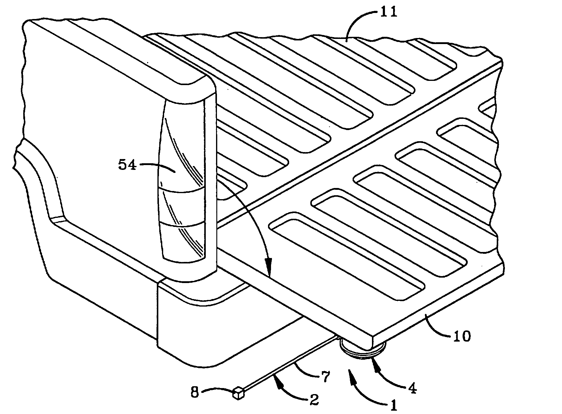
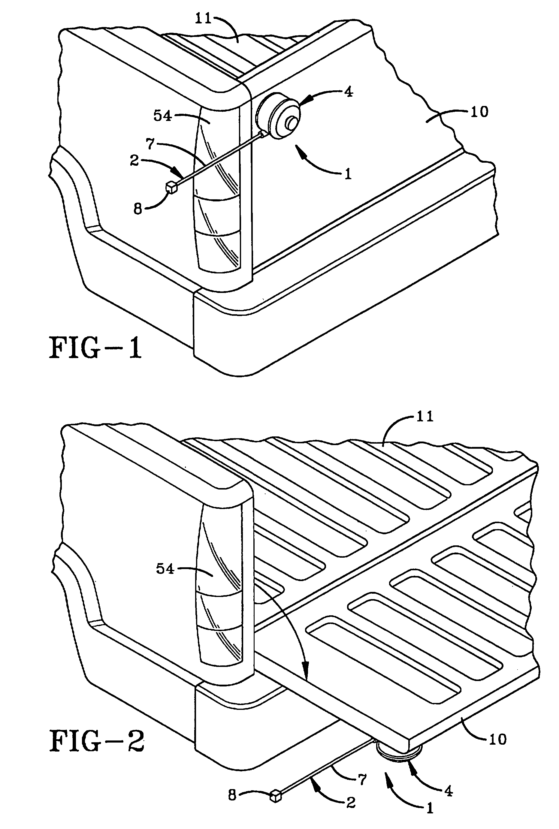
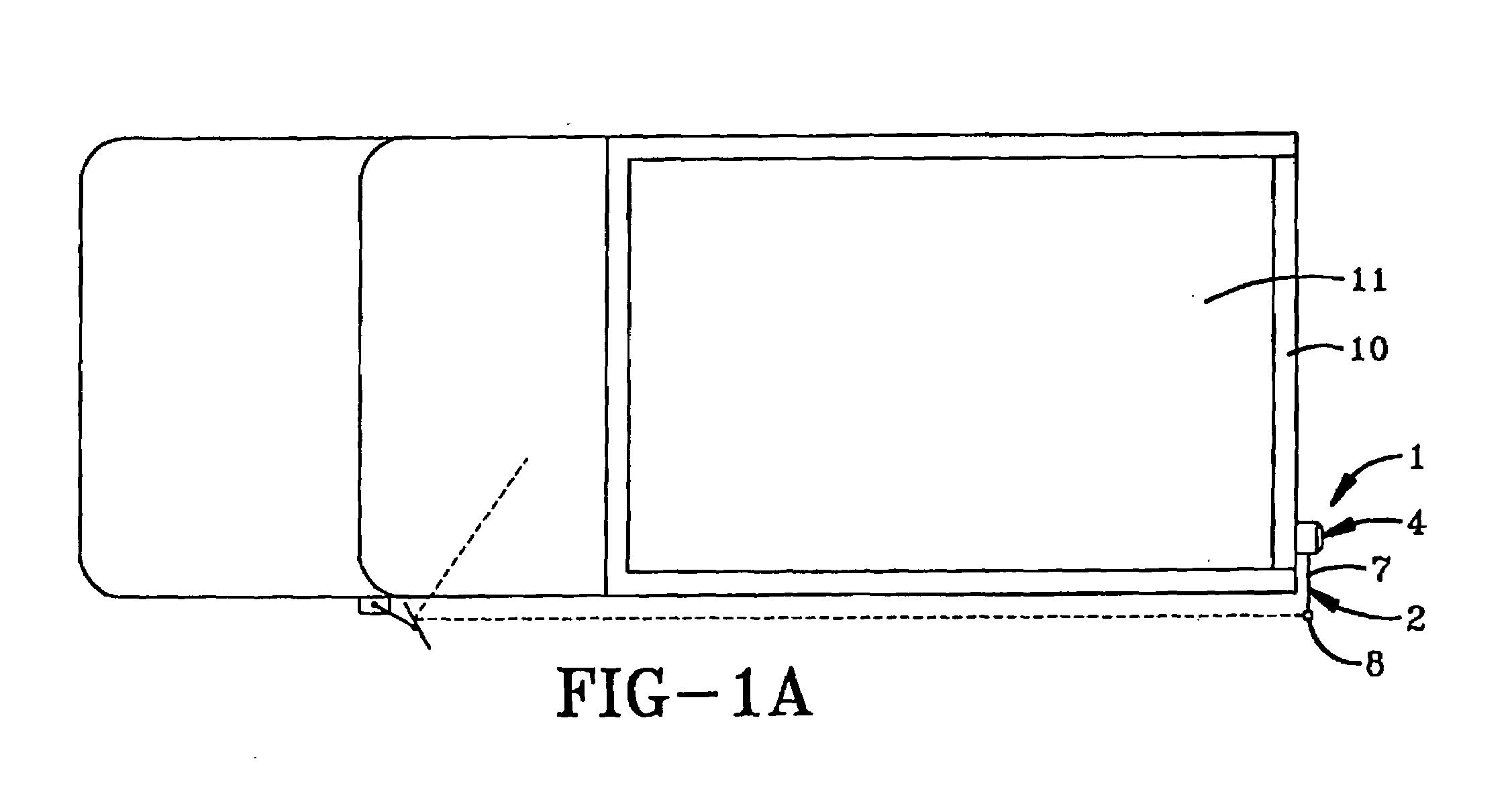
first embodiment
[0055]A second alternative embodiment of the improved tailgate position indicator of the present invention is indicated generally by the numeral 100 in FIGS. 8 through 13. As in the invention, tailgate position indicator 100 includes an indicator assembly 102 and a housing assembly 104. Housing assembly 104 is adapted to receive and hold indicator assembly 102 in an adjustable manner such that the length of indicator assembly 102 that extends from housing assembly 104 may be varied.
[0056]Indicator assembly 102 includes an indicator rod 107 which carries at a first end a first indicator body 108 and carries at a second end a second indicator body 108′. Indicator rod 107 is in the form of a tightly wound spring of steel, although alternative materials may be employed. Indicator assembly 102 passes through housing assembly 104 such that indicator bodies 108 and 108′ are disposed on either side of housing assembly 104.
[0057]Housing assembly 104 includes a block 112, a plunger 106, an ad...
third embodiment
[0060]the present invention is indicated generally by numeral 201 in FIGS. 14 through 16. Tailgate position indicator 201 includes an indicator assembly 202 carried by and extending from a housing block 212. Indicator assembly 202 includes an indicator rod 207 having a first end carrying a first indicator body 208 and having a second end carrying a second indicator body 208′. Indicator rod 207 is resilient and may be fabricated from a tightly wound spring of steel, although alternative materials may be used that are resilient.
[0061]Housing block 212 defines a first channel 216, a second channel 214, and a third channel 218 with second channel 214 connecting first channel 216 with third channel 218 to form a continuous channel through block 212. A first surface 217 of block 212 defines first channel 216. A second surface 215 of block 212 defines second channel 214. As may be seen in the drawings, second surface 215 connects with the outer surface of block 212 such that a portion of s...
fourth embodiment
[0066]the present invention is indicated generally by the numeral 300 in FIGS. 17–21. Tailgate position indicator 300 includes an indicator assembly 302 carried by and extending from a housing block 312. Indicator assembly 302 includes an indicator rod 307 having a first end carrying a first indicator body 308 and having a second end carrying a second indicator body 308′. Indicator rod 307 is preferably fabricated from a light-transmitting material and is in the form of an elongated rod having a substantially circular cross-section. Indicator rod 307 may be substantially rigid but may also be fabricated to flex so that it will not break if accidentally hit against another object. In other embodiments of the invention, indicator rod 307 may be fabricated from an opaque plastic or a metal.
[0067]Each indicator body 308 and 308′ preferably includes a plurality of substantially planar faces that cooperate together to form a substantially round surface. The faces of indicator bodies 308 a...
PUM
 Abstract
Description
Claims
Application Information