Dispensing closure with automatic sealing valve of single body

a technology of automatic sealing valve and closure, applied in the field of closure, can solve the problems of continuous dislodgement of automatic sealing valve, upward dislodgement, and inconvenient operation, and achieve the effect of tighter engagement, reduced manufacturing defect and disorder, and more effective sealing

Active Publication Date: 2006-10-31
CHONG WOO
View PDF9 Cites 32 Cited by
  • Summary
  • Abstract
  • Description
  • Claims
  • Application Information

AI Technical Summary

Benefits of technology

[0019]One of important features of the present invention is that the automatic sealing valve can be securely engaged to the closure body without requiring any retaining means, such as a retaining ring in prior art, and is not dislodged from the closure body during use due to their special structural configuration. Furthermore, this structural configuration provides tighter engagement and more effective sealing than any structural configurations in prior art. In addition, the reduced number of constitutional elements, based upon this structural configuration, can significantly reduce the possibility of defect in manufacture and disorder in use as well as the manufacturing cost.

Problems solved by technology

However, this structural configuration has some drawbacks as below.
First, the structural configuration according to the above patent requires the retaining ring.
Nevertheless, the possibility of dislodgement of the automatic sealing valve continuously exists because the self-sealing valve is so flexible that it can be too largely deformed during operation, thereby causing the upwardly dislodgement thereof.
Moreover, where a defect occurs in the retaining ring in a manufacturing and / or assembling processes, it is very difficult to disassemble the retaining ring without causing any damage in the automatic sealing valve, because the retaining ring need to be strongly attached to the dispense closure for preventing the possibility of dislodgement as described above.
Second, the structural configuration according to the above patent also requires the separate, supporting member to prevent the automatic sealing valve from being downwardly dislodged during operation.
The need of the retaining ring and supporting member for configuration of dispensing closure causes complication of manufacturing and assembling steps, which also causes the possibility of its defect and disorder as well as the manufacturing cost to increase.

Method used


Image

  • Dispensing closure with automatic sealing valve of single body
  • Dispensing closure with automatic sealing valve of single body
  • Dispensing closure with automatic sealing valve of single body

Examples


Embodiment Construction

[0025]While the present invention is susceptible of embodiment in many different forms, this specification and accompanying drawings disclose only some specific forms as examples of the invention. Accordingly, the present invention is not intended to be limited to the embodiments so described.

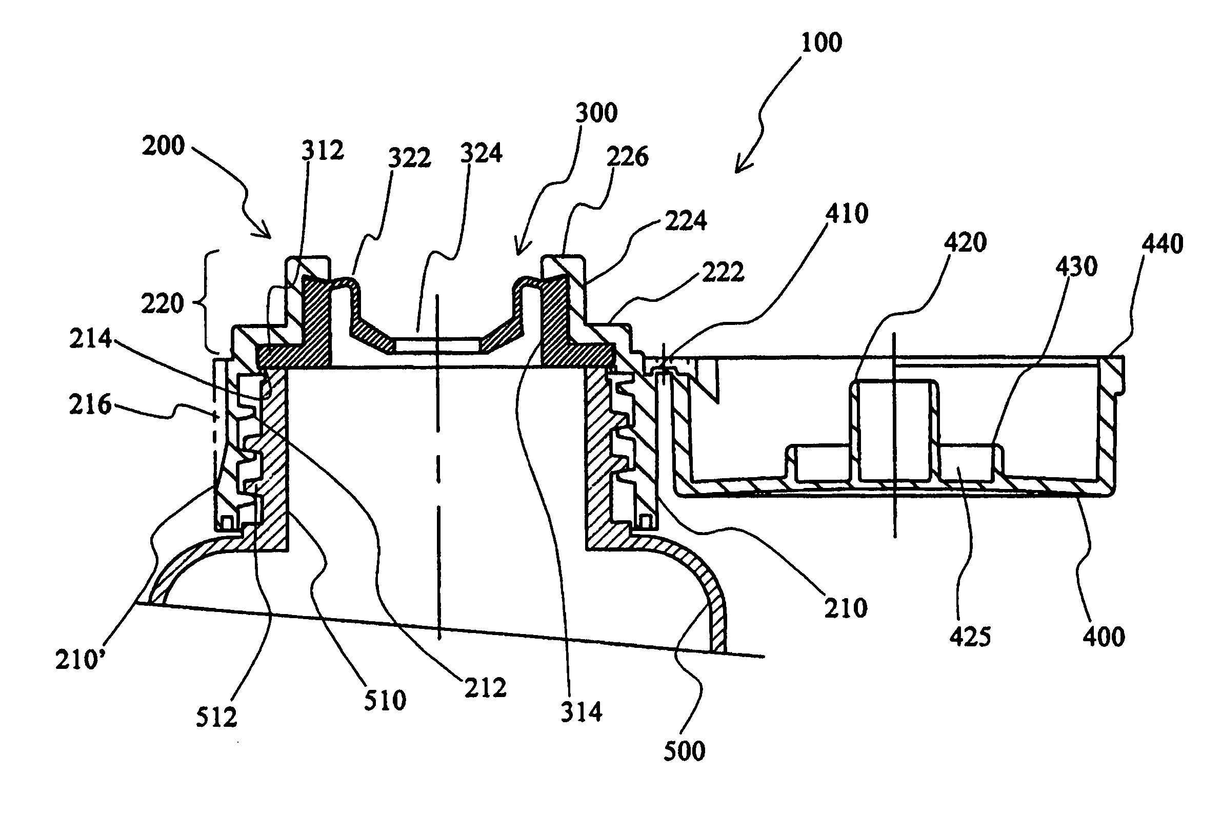
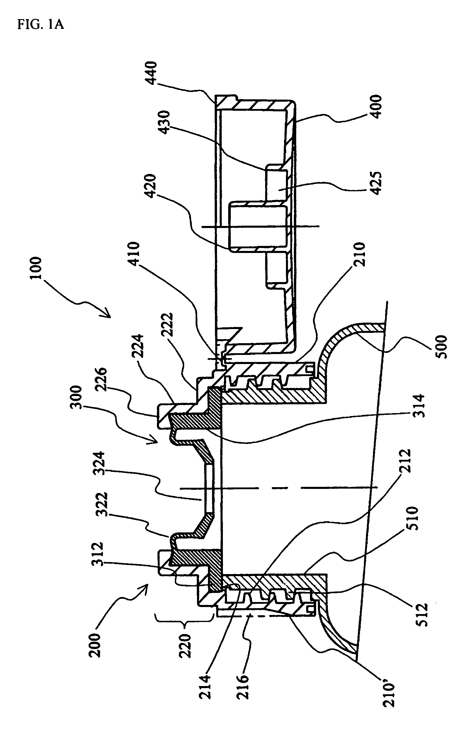
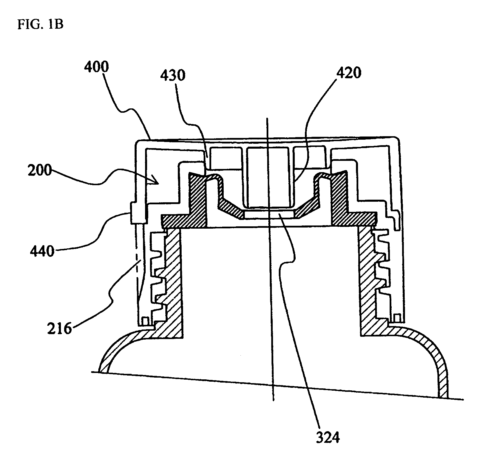
[0026]FIGS. 1A and 1B illustrate a cross-sectional side view of a particular embodiment of a dispensing closure 100 according to the present invention, in an open cap position and closed cap position, respectively. The dispensing closure 100 in FIGS. 1A and 1B comprises a closure body 200 and an automatic sealing valve 300, and a cap 400 is connected to the closure body 200 through a snap hinge 410.

[0027]The closure body 200 generally comprises a cylindrical body 210 and a tubular spout 220. The cylindrical body 210 is attached to an opening 510 of a container 500. For tight attachment, the cylindrical body 210 includes an internal thread 212 for threadedly attaching the closure body 200 to an ...


PUM


Abstract

The present invention relates to a dispensing closure which includes an automatic sealing valve which opens to dispense a fluid product from a squeeze-type container when the container is subjected to an external force, such as squeezing pressure, and which automatically closes when the external force is terminated, and a closure body which securely mounts the automatic sealing valve to the container, wherein the automatic sealing valve and the closure body are designed in a special form not to need a means for retaining the automatic sealing valve to the closure body, so that the possibilities of defect thereof in manufacture and disorder during use can be remarkably reduced, and the manufacturing cost can be reduced by shortening an assembling process.

Description

TECHNICAL FIELD[0001]The present invention relates generally to closures, and more particularly to a dispensing closure which includes an automatic sealing valve which opens to dispense a fluid product from a squeeze-type container when the container is subjected to an external force, such as squeezing pressure, and which automatically closes when the external force is terminated, and a closure body which securely mounts the automatic sealing valve to the container, wherein the automatic sealing valve and the closure body are designed in a special form not to need a means for retaining the automatic sealing valve to the closure body, so that the possibilities of defect thereof in manufacture and disorder during use can be remarkably reduced, and the manufacturing cost can be reduced by shortening an assembling process.BACKGROUND OF THE INVENTION[0002]Dispensing devices, discharging a predetermined amount of fluid product in a container when required, have been developed in a variety...

Claims


Application Information

Patent Timeline
Patent Type & Authority Patents(United States)
IPC IPC(8): B65D37/00B65D47/08B65D47/20B65D41/16
CPCB65D47/0809B65D47/2031B65D41/16
Inventor LEE, CHUNG KEE
Owner CHONG WOO
Why Eureka
Try Eureka