Suction cup device

a technology of suction cup and lever, which is applied in the direction of shaving accessories, other domestic objects, machine supports, etc., can solve the problems of troublesome assembly of suction lock/release lever, unsatisfactory disengagement of suction cup device b>10/b> from the flat wall, and complicated adjustment, etc., to achieve convenient operation, reduce pressure, and tight engagement with the flat surface

Inactive Publication Date: 2011-12-20
TU TSUNG TZONG +1
View PDF10 Cites 17 Cited by
  • Summary
  • Abstract
  • Description
  • Claims
  • Application Information

AI Technical Summary

Benefits of technology

[0007]An object of the present invention is to provide a suction cup device which can produce a reduced pressure with an adjustable and desired suction strength to ensure tight engagement with a flat surface, and which can be assembled and operated conveniently.

Problems solved by technology

However, in the conventional suction cup device 10, the strength of suction force generated as a result of movement of the central part of the suction cup 13 is constant, and cannot be increased after a period of use, thereby resulting in undesired disengagement of the suction cup device 10 from the flat wall 1.
However, assembly of the suction lock / release to the lever is troublesome.
Besides, manual operation of the suction lock / release is required to lock or unlock the lever, thereby rendering the adjustment complicated.

Method used


Image

  • Suction cup device
  • Suction cup device
  • Suction cup device

Examples


Embodiment Construction

[0018]Before the present invention is described in greater detail, it should be noted that same reference numerals have been used to denote like elements throughout the specification.

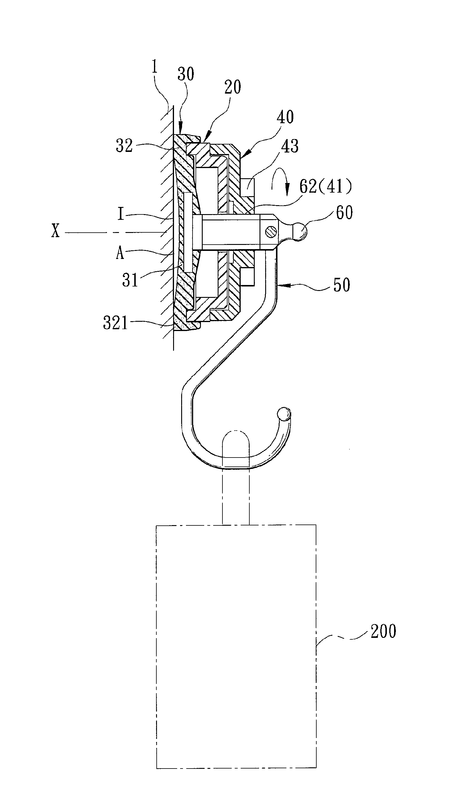
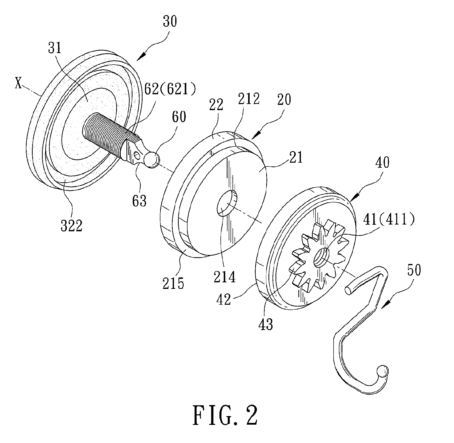
[0019]Referring to FIGS. 2 to 5, the first preferred embodiment of a suction cup device according to the present invention is shown to comprise a cup forming unit 30, a liftable rod 60, a bracing shell member 20, and a twistable cap member 40.

[0020]The cup forming unit 30 is adapted to confront a flat surface (I), such as of a vertical wall 1, and defines a central axis (X) normal to the flat surface (I) to cooperate therewith to create a volume-variable space (A). In this embodiment, the cup forming unit 30 is made from an elastic material to be of a single-piece structure, and has a central portion 31 and a peripheral portion 32. The central portion 31 has suction-side and pull-side central surfaces 311, 312 opposite to each other in a direction of the central axis (X). When the central portion 31 is ...


PUM


Abstract

A suction cup device includes a cup forming unit cooperating with a flat surface to create a volume-variable space, a liftable rod secured to a central portion of the cup forming unit, a bracing shell member having a force-transmitting surrounding wall in engagement with a peripheral portion of the cup forming unit, and a twistable cap member having a surrounding bottom wall in abutting against a circumferential abutment region of the bracing shell member and threadedly engaged with the liftable rod such that a manually twisted movement of the twistable cap member can result in axial movement of the rod so as to pull the central portion away from the flat surface to produce a reduced pressure in the volume-variable space and a biasing force to thereby ensuring fluid-tight engagement of the cup forming unit with the flat surface.

Description

CROSS-REFERENCE TO RELATED APPLICATION[0001]This application claims priority of Taiwanese Utility Model Application No. 099200353, filed on Jan. 8, 2010, the disclosure of which is herein incorporated by reference.BACKGROUND OF THE INVENTION[0002]1. Field of the Invention[0003]This invention relates to a suction cup device, more particularly to a suction cup device which defines a volume-variable space to produce an adjustable reduced pressure with a desired suction strength.[0004]2. Description of the Related Art[0005]FIG. 1 shows a conventional suction cup device 10 disclosed in U.S. Patent Publication No. US 2010 / 0116954 A1, which is adapted to be attached to a flat wall 1, and which includes a suction cup 13 with a rack 14 connected to the center thereof, a mount body 11 attached to the suction cup 13 by virtue of a pressing ring 12, and a lever 15 pivotably mounted on the mount body 11 and provided with a pinion 152 meshing with the rack 14. By turning the lever 15, a central p...

Claims


Application Information

Patent Timeline
Patent Type & Authority Patents(United States)
IPC IPC(8): A45D42/14
CPCF16B47/006
Inventor TU, TSUNG-TZONGTU, TSUNG-AN
Owner TU TSUNG TZONG
Why Eureka
Try Eureka