
Automotive knee bolster installation and method of construction

a knee bolster and automobil technology, applied in the field of knee bolsters, can solve the problems of large extrusions themselves, high construction costs, and still somewhat expensive structures to manufacture, and achieve the effects of preventing any interference with the steering column mechanism, reducing construction costs, and providing adequate resistance to deformation

Active Publication Date: 2006-10-31
INDUS CONCEPT & ENG
View PDF10 Cites 14 Cited by
  • Summary
  • Abstract
  • Description
  • Claims
  • Application Information

AI Technical Summary

Benefits of technology

"The patent describes a knee bolster for a steering column that absorbs impact during a collision to protect the driver. The bolster consists of two laterally spaced knee impact absorber structures, each made of plastic or aluminum extruded material. The structures have a unique geometry that creates an upper stabilizer and a lower stabilizer to guide the driver's knees away from the steering column. The inner and outer strips on the structures help to absorb the impact and deform the structures without collapsing or intruding into the area where the steering column passes. The upper stabilizer prevents outward buckling collapse of the outer strips and maintains resistance to deformation throughout the crush event. Overall, the knee bolster provides effective protection for the driver during a collision."

Problems solved by technology

Costs are always a problem in automotive design, and the knee bolsters have sometimes been assembled from a number of components, representing an assembly cost.
Large extrusions are themselves costly such that these structures are still somewhat expensive to manufacture.
Other knee bolsters have involved crush cells which have curved webs which are deformed, but such webs have a geometry which results in a buckling collapse of the web, greatly reducing the structure's ability to absorb energy.
This can result in a great reduction in the restraining resistance of the structure.
Such collapse can also produce gross bulging which can interfere with proper operation of the steering mechanism.
Also, such a collapse mode can cause the surface impacted by the knees to directly hit the steering column and hinder the proper functioning of the steering column.

Method used


Image

  • Automotive knee bolster installation and method of construction
  • Automotive knee bolster installation and method of construction
  • Automotive knee bolster installation and method of construction

Examples


Embodiment Construction

[0032]In the following detailed description, certain specific terminology will be employed for the sake of clarity and a particular embodiment described in accordance with the requirements of 35 USC 112, but it is to be understood that the same is not intended to be limiting and should not be so construed inasmuch as the invention is capable of taking many forms and variations within the scope of the appended claims.

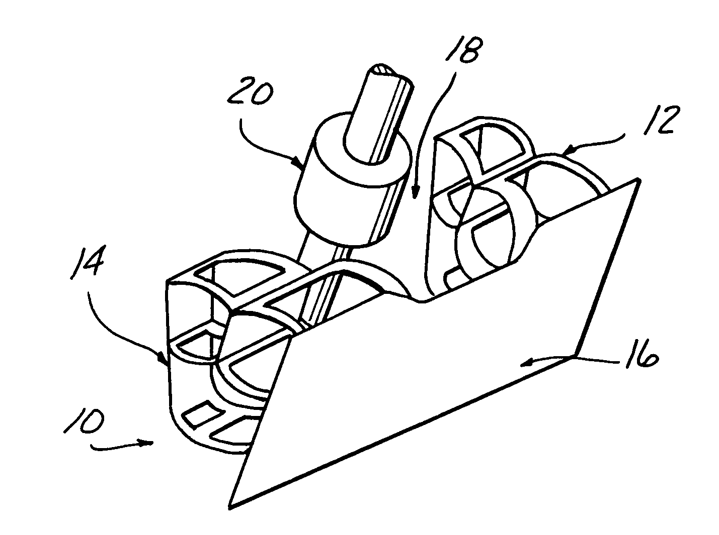
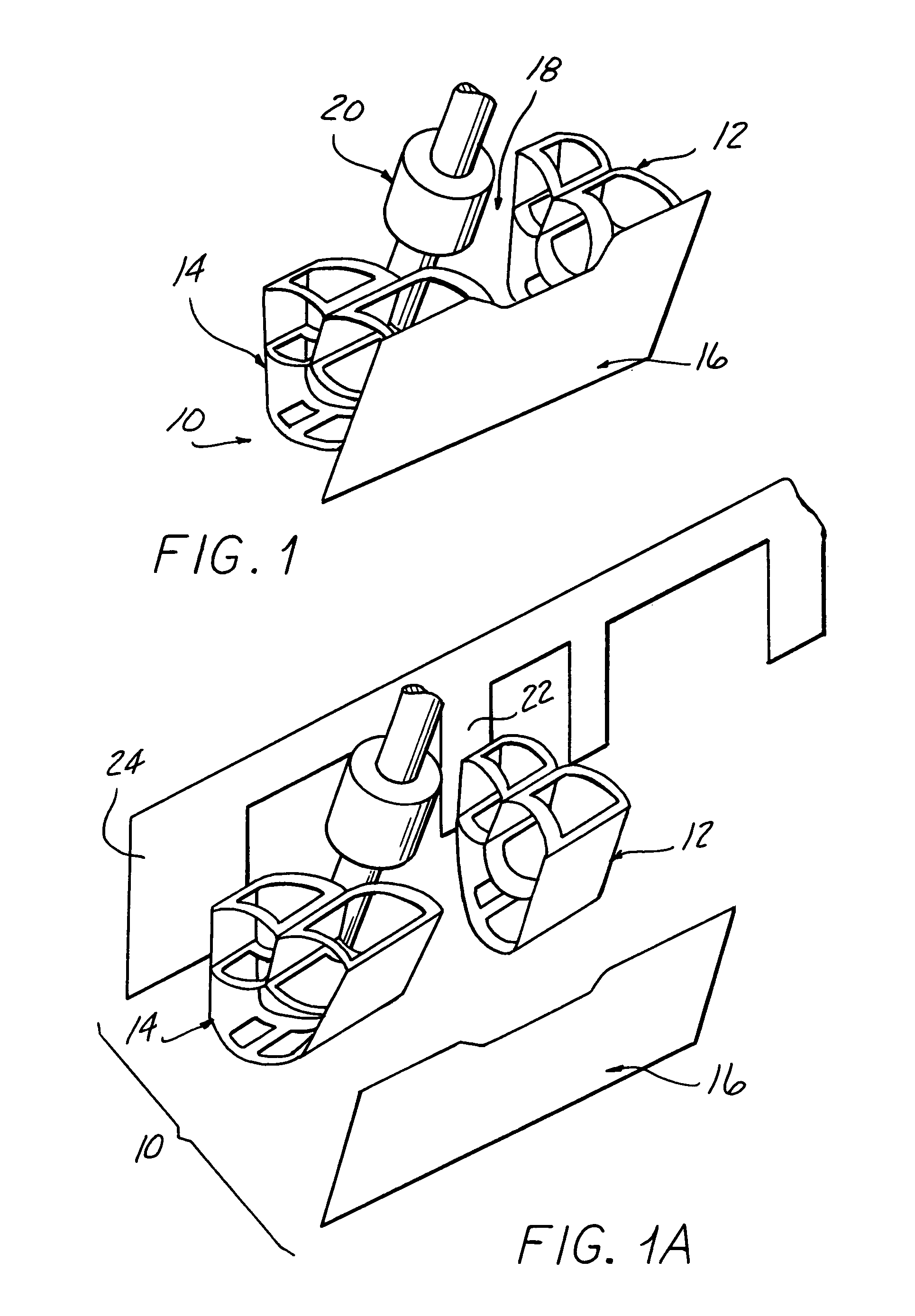
[0033]Referring to the drawings, and particularly FIGS. 1 and 1A, the knee bolster 10 according to the present invention includes a right knee impact absorber structure 12 and a left knee impact absorber structure 14, both attached to a respective end of a bridging plate 16 extending between the driver's seat and the structures 12 and 14 and facing the driver's knees. A space 18 between the absorber structures 12, 14 accommodates the steering column 20 of the vehicle in which the knee bolster 10 is installed.

[0034]The absorber structures 12 and 14 are each restrained by ...


PUM


Abstract

A knee bolster installation for an automotive vehicle includes a bridge plate extending across a space receiving a steering column in front of the driver's knee and having a knee impact absorber structure attached behind each end of the bridge plate. Each knee impact absorber structure has diverging front and back walls having a curve top wall and a curved intermediate web extending between the front and back walls, and a curved bottom connecting the lower end of front and back walls together. A horizontal stabilizer web connects the top wall and intermediate web together to restrain bulging when crushed to avoid horizontal collapse thereof during deformation. Offset openings in each of the top wall, intermediate web, and bottom wall form wider curved strips at the inside adjacent the steering column space so that the front of the outside ends of the knee installation absorber structures are inclined away from the steering column space when deformed by knee impact. The knee installation absorber structures are preferably extruded and the openings thereafter cut into the top wall, intermediate web and bottom wall.

Description

CROSS REFERENCE TO RELATED APPLICATION[0001]This application claims the benefit of U.S. provisional Ser. No. 60 / 417,431, filed Oct. 10, 2002.BACKGROUND OF THE INVENTION[0002]This invention concerns so called “knee bolsters”, which are structures installed in automotive vehicles forward of the driver's seat positioned to be engaged by the driver's knees if the person submarines below the steering wheel mounted air bag during a collision.[0003]Knee bolsters sometimes employ crushable or deformable impact absorbing structures which restrain the driver by contact by his or her knees, the crushing of the structure absorbing the energy of the person's momentum over a range of deformation to lower the stress on the person's knees and the load transmitted to the thigh bone.[0004]Deformable structure knee bolsters are designed to be crushed by the person as the person is decelerated by the collision in order to reduce or prevent injury to the person.[0005]Another requirement is the preventio...

Claims


Application Information

Patent Timeline
Patent Type & Authority Patents(United States)
IPC IPC(8): B60R21/045
CPCB60R21/045B60R2021/0051
Inventor MANI, AYYAKANNU
Owner INDUS CONCEPT & ENG
Learn More