Transpiration cooling system

a cooling system and transpiration technology, applied in the direction of non-positive displacement fluid engines, liquid fuel engine components, safety/emergency devices, etc., can solve the problems of difficult cooling of transpiration cooling systems in particularly harsh environments, uneven distribution of porosity in materials, and inability to select other selected or desirable characteristics

Active Publication Date: 2006-10-31
THE BOEING CO
View PDF8 Cites 19 Cited by
  • Summary
  • Abstract
  • Description
  • Claims
  • Application Information

AI Technical Summary

Benefits of technology

[0009]The invention further provides a system for cooling a component through substantially transpiration processes. A laminate material including required physical characteristics, such as strength or toughness, and including selected pores, is provided adjacent or around the apparatus to be cooled. The selected pores allow for transpiration of a coolant which can be flowed between the porous material and the apparatus to be cooled or the source of the heat flux. The coolant, which is transpirated through the porous member or structure, absorbs thermal energy from the apparatus to be cooled or heat source. This removes thermal energy from the apparatus and allows a selected temperature of the apparatus to be maintained during operation of the apparatus. Therefore, only the coolant material and an area for the coolant material to flow is required between the apparatus and the porous membrane. Thus, a small system is provided for cooling the selected apparatus.

Problems solved by technology

Although porosity for various materials may be within a generally known range, the porosity can be unevenly distributed throughout the material.
Furthermore, a material having a selected porosity may not include other selected or desirable characteristics, such as strength.
Cooling these systems in particularly harsh environments can be difficult due to the high heat flux, strength, and heat resistance needed of the various cooling components.
Therefore, providing a cooling system in such an environment is often difficult, heavy, complex, or expensive.
In addition, the cooling systems are generally large and bulky due to the requirements for heat transfer and strength in the environment.

Method used


Image

  • Transpiration cooling system
  • Transpiration cooling system
  • Transpiration cooling system

Examples


Embodiment Construction

[0020]The following description of various embodiments is merely exemplary in nature and is in no way intended to limit the invention, its application, or uses.

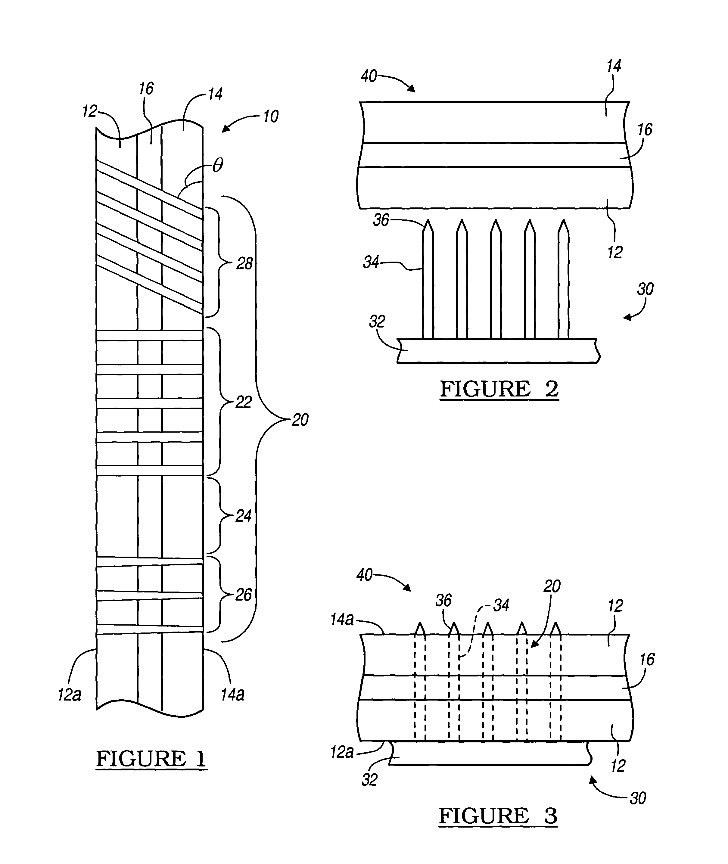
[0021]With reference to FIG. 1, a laminated structure 10 includes at least two layers, a first layer 12 and a second layer 14 formed generally adjacent one another. In addition, an intermediate layer 16 may be formed or positioned between the first and second layers 12, 14. The intermediate layer 16 may be used for adhering the first and second layers 12, 14 to one another during a formation or laminating process. Nevertheless, it will be understood that laminated layers may include a pre-impregnated material which can be used to affix the first and second layers 12, 14 together during the formation process. Alternatively, the first and second layers 12, 14 may be fixed to one another, during the formation process, without any additional adhesive material. Also, it will be understood that the laminate structure 10 may include...


PUM


Abstract

A system for cooling a structure or mechanism through transpiration processes. Generally a porous structural material may be used to form a hot wall surface of a high temperature or high heat flux environment component, typically used in combustion type devices. Coolant pressurized on the “cold” or cooler side of the wall is bled, “sweated”, or otherwise transpired to the “hot” wall surface in an effort to control the hot wall surface temperature by shielding the surface with a coolant layer at the surface and by removing heat via coolant flow past the surface. This may be done to manage the hot wall temperature for structural purposes, more effectively manage high heat fluxes, or to hide thermal signatures. The porous material can be selectively made such that the coolant material flows substantially in one direction only through the porous material to transfer thermal energy only away from the structure rather than towards the structure.

Description

FIELD OF THE INVENTION[0001]The present invention relates generally to cooling systems for transpiration cooling, and particularly to systems and methods of forming selectively porous laminate materials for transpiration cooling.BACKGROUND OF THE INVENTION[0002]Many materials are known to be porous, generally being inherently porous. The naturally porous materials can be provided as filters or as transpiration coolers for various applications. Nevertheless, many natural materials include a porosity that is also substantially “natural”. Simply, the natural porosity of many materials is highly variable. Although porosity for various materials may be within a generally known range, the porosity can be unevenly distributed throughout the material. Moreover, the natural porosity of a selected material may be within a large range rather than within a narrow porosity range. Furthermore, a material having a selected porosity may not include other selected or desirable characteristics, such ...

Claims


Application Information

Patent Timeline
Patent Type & Authority Patents(United States)
IPC IPC(8): F01D5/18F04D29/58B64C1/38B64C3/36B64G1/58F01D25/12F02K1/82F02K9/40F02K9/64F04D29/38F23R3/00
CPCB64C1/38B64G1/58F01D5/184F01D25/12F02K1/825F02K9/64F02K9/972F23R3/002F23R3/007F28F13/003F42B15/34B64G1/401Y02T50/433F23R2900/03041F28D2021/0078F05D2250/323Y02T50/40
Inventor PETERVARY, MIKLOS PAULLOHNER, KEVIN A
Owner THE BOEING CO
Why Eureka
Try Eureka