
Electrical connector

a technology of electrical connectors and connectors, applied in the direction of coupling device connections, coupling contact members, engagement/disengagement of coupling parts, etc., can solve the problems of allowing incorrect insertion, difficult to provide irregularities on the contact, and the housing adjacent to the contact insertion end so as to prevent incorrect insertion of the contact. , the effect of smooth insertion

Active Publication Date: 2006-10-31
TYCO ELECTRONICS JAPAN GK
View PDF10 Cites 7 Cited by
  • Summary
  • Abstract
  • Description
  • Claims
  • Application Information

AI Technical Summary

Benefits of technology

[0007]It is therefore an object of the invention to provide an electrical connector that allows a contact to be smoothly inserted into the contact receiving opening when the contact receiving opening has varying dimensions and prevents incorrect insertion of the contact.

Problems solved by technology

When the contact is incorrectly or inversely inserted into the housing, particularly in the case of a substantially square contact, failure of engagement of the electrical connector with a mating connector is likely to occur.
Because the contact insertion end must be large enough to accommodate the larger end of the contact, it is difficult to provide irregularities on the contact and the housing adjacent to the contact insertion end to prevent incorrect insertion of the contact.
However, the front edge of a small projection may easily scrape by an inner wall of the housing, allowing incorrect insertion.
Further, even when the contact is inserted correctly, it is difficult to have the contact smoothly transition between the differently dimensioned areas within the housing.
This is especially difficult when the electrical connector is connected to a wire having a cross section of about 0.22 to 0.5 mm.

Method used


Image

  • Electrical connector
  • Electrical connector
  • Electrical connector

Examples


first embodiment

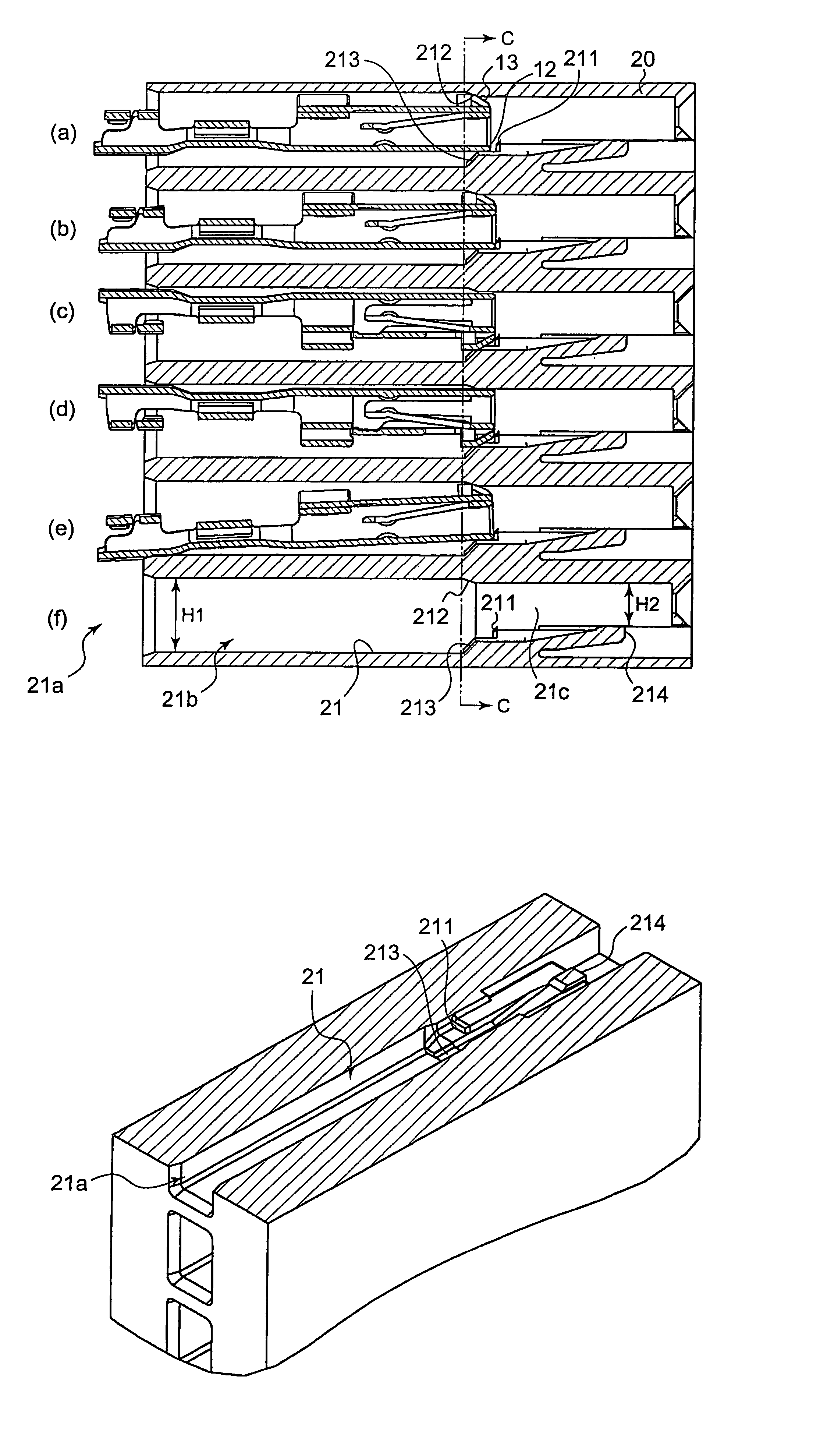
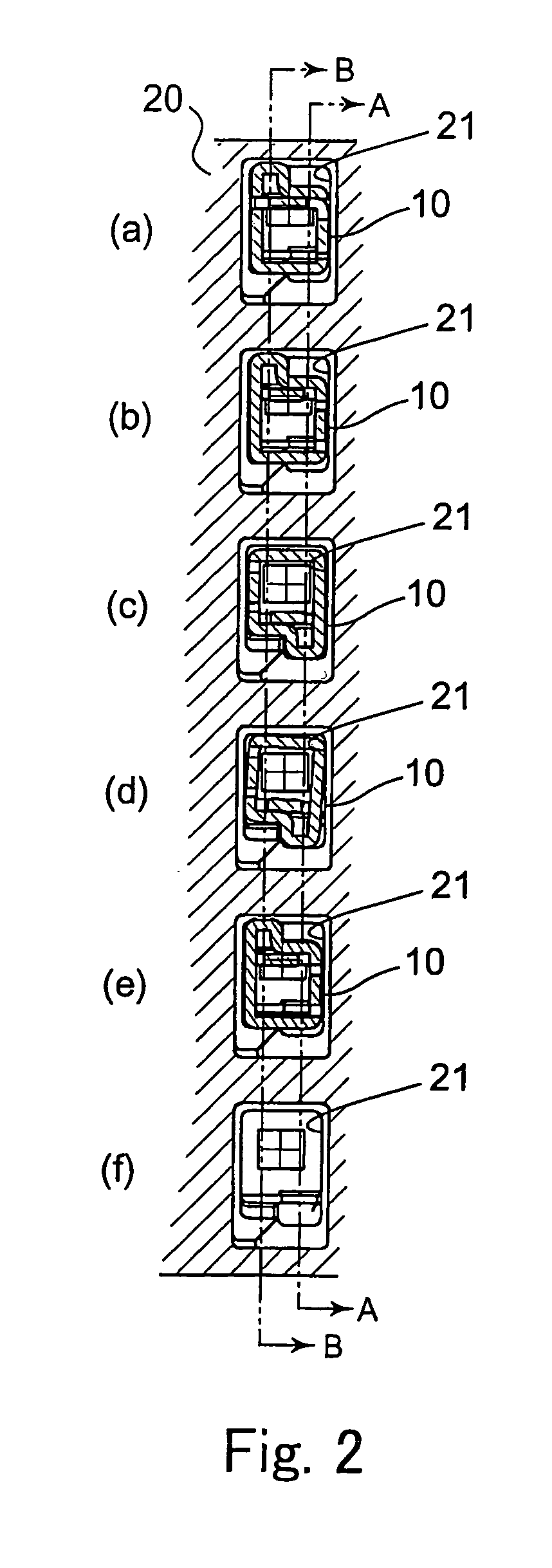
[0030]FIGS. 2–7 show an electrical connector according to the invention. As shown in FIG. 2, the electrical connector includes a housing 20 having contact receiving openings 21. Although the contact receiving openings 21 are illustrated as being arranged in a single column, it will be appreciated by those skilled in the art that the contact receiving openings 21 may also be arranged in a matrix. As shown in FIGS. 3–4, each of the contact receiving openings 21 has a contact insertion end 21a. The contact receiving openings 21 comprise a first area 21b and a second area 21c. The first area 21b is beside the contact insertion end 21a and has a height H1. The first area accommodates a wire (not shown) connected to the contact 10. The second area 21c has a height H2 that is smaller than the height H1 and accommodates the contact 10.

[0031]As shown in FIGS. 3 and 7, the contact receiving opening 21 is provided with a projection 211, a first bevelled surface 212, a second bevelled surface 2...

second embodiment

[0039]The method of inserting the contact 10 into the electrical connector will now be explained with reference to FIGS. 8A–11B.

[0040]FIGS. 8A–8B show the contact 10 inversely inserted halfway into the contact receiving opening 21 of the housing 20. In this position, the inclined portion 13 of the contact 10 interferes with the first bevelled surface 212 of the contact receiving opening 21. The contact 10 is therefore subjected to a force perpendicular to a direction of insertion. As shown in FIGS. 9A–9B, when the contact 10 is inserted further, the abutment edge 12 abuts the projection 211 so that the contact 10 can not be inserted further into the contact receiving opening 21. Incorrect insertion of the contact 10 into the contact receiving opening 21 is therefore prevented.

[0041]FIGS. 10A–10B show the contact 10 correctly inserted halfway into the contact receiving opening 21 of the housing 20. The inclined portion 13 of the contact 10 interferes with the second bevelled surface...


PUM


Abstract

An electrical connector comprises a contact having a wire connection member and a mating contact receiving end. The mating contact receiving end includes an abutment edge and an inclined portion. A housing has a contact receiving opening with a contact receiving end. The housing has a projection extending into the contact receiving opening and a first bevelled surface opposing the projection. The first bevelled surface is arranged closer to the contact receiving end than the projection. The inclined portion engages the first bevelled surface to bias the abutment edge into the projection when the contact is incorrectly inserted into the contact receiving opening.

Description

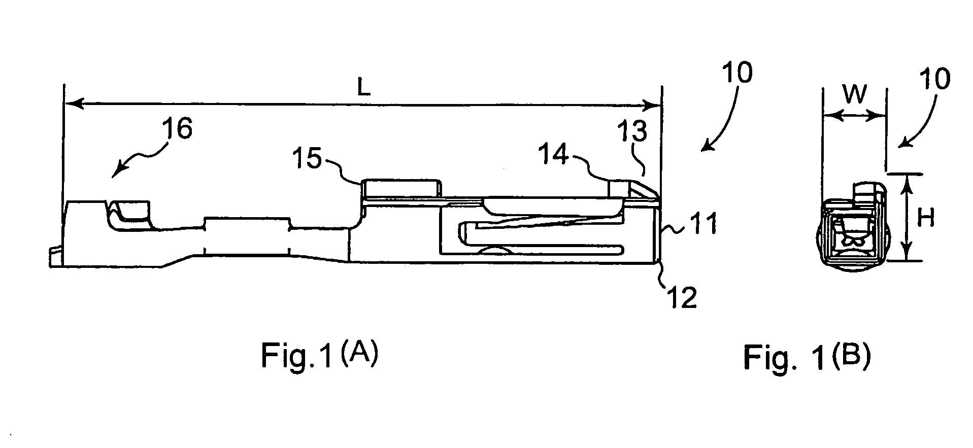
FIELD OF THE INVENTION[0001]The invention relates to an electrical connector having a housing formed to prevent incorrect insertion of a contact therein.BACKGROUND OF THE INVENTION[0002]Traditionally, an electrical connector is assembled by inserting a contact into a contact receiving opening provided in a housing. When the contact is incorrectly or inversely inserted into the housing, particularly in the case of a substantially square contact, failure of engagement of the electrical connector with a mating connector is likely to occur. In order to prevent incorrect insertion, the contact and / or the housing have been formed with irregularities that only allow the contact to be inserted into the housing in the correct direction.[0003]For example, Japanese Patent Publication No. 10-144379 teaches a housing having a step disposed on an inner wall of a contact receiving opening and a contact with a projection that abuts the step when it is inversely inserted into the housing. In additio...

Claims


Application Information

Patent Timeline
Patent Type & Authority Patents(United States)
IPC IPC(8): H01R13/40H01R13/514
CPCH01R13/4223
Inventor SAKAMAKI, KAZUSHIGEMINAKATA, MASATOKOBAYASHI, HIROSHINISHIDA, ATSUSHI
Owner TYCO ELECTRONICS JAPAN GK
Learn More