Non-contact waveform monitor

a non-contact, waveform monitor technology, applied in the field of non-contact waveform monitors, can solve the problems of patient distress, long felt but unsolved need to continuously and and inability to accurately monitor blood pressure waveforms without contact,

Active Publication Date: 2006-10-31
THE UNITED STATES OF AMERICA AS REPRESENTED BY THE SECRETARY OF THE NAVY
View PDF11 Cites 61 Cited by
  • Summary
  • Abstract
  • Description
  • Claims
  • Application Information

AI Technical Summary

Benefits of technology

[0031]The non-contact method may further comprise analyzing the blood pressure waveform representation to determine systolic time interval parameters and/or analyzing the blood pressure waveform parameters to determine heart rate and/or comparing systolic time interval parameters estimated utilizing th

Problems solved by technology

For decades, there has been a long felt but unsolved need to continuously and accurately measure physiological events such as blood pressure without making contact with the patient.
For many patients, such as burn victims, neonates, and for patients who need to be monitored without disturbing sleep or rest, the ability to accurately monitor blood pressure waveforms without contact has long been desired, but never accomplished.
However, due to the requirement of inserting these sensors into the arterial system, the patient may be placed in distress.
This method provides only systolic and diastolic pressure values for a moment in time and does not provide time-continuous pressure measurements.
However, contact must be made with the subject and so a non-contact method for measuring blood pressure is not disclosed.
However, such techniques are co

Method used


Image

  • Non-contact waveform monitor
  • Non-contact waveform monitor
  • Non-contact waveform monitor

Examples


Embodiment Construction

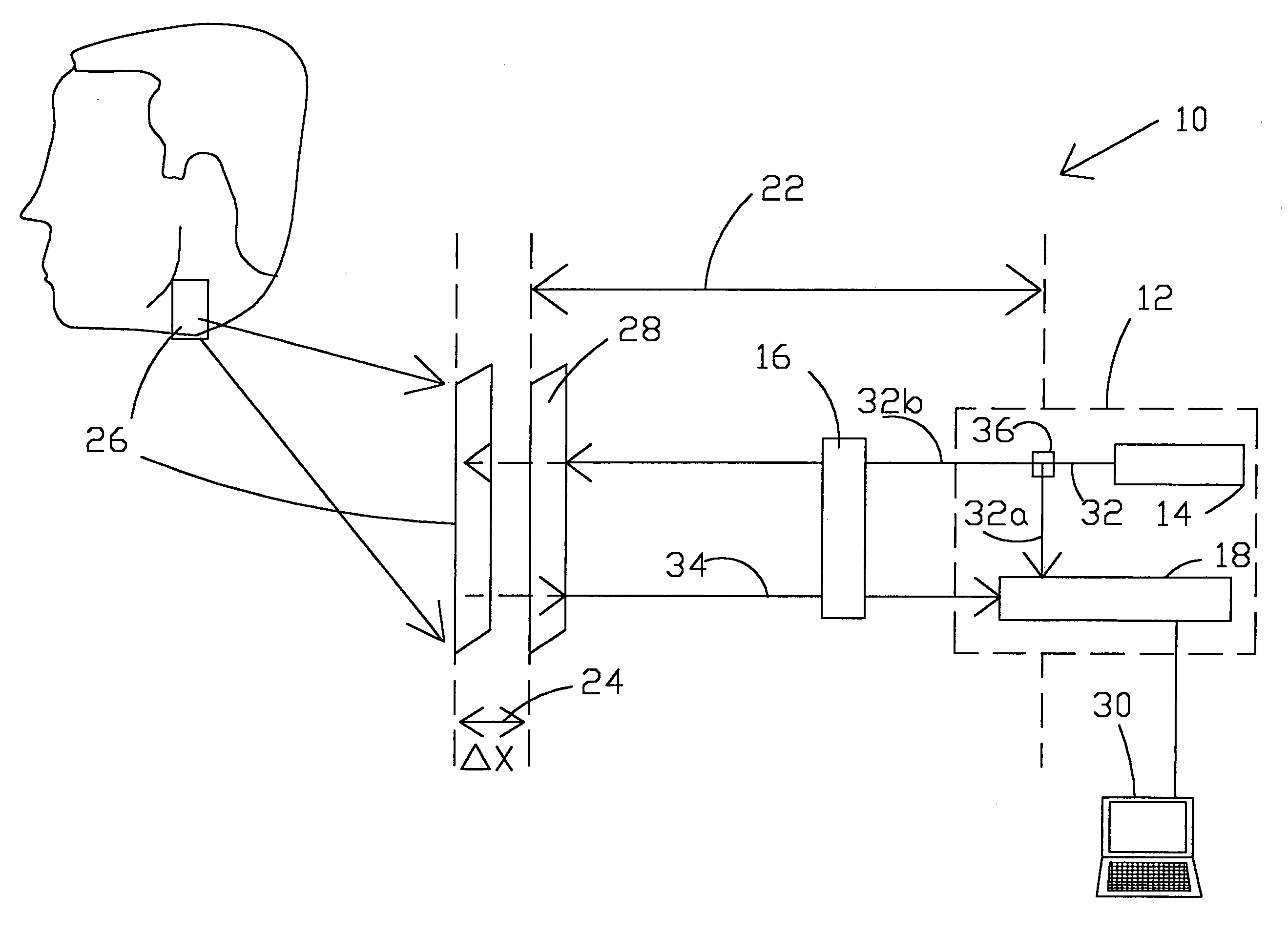
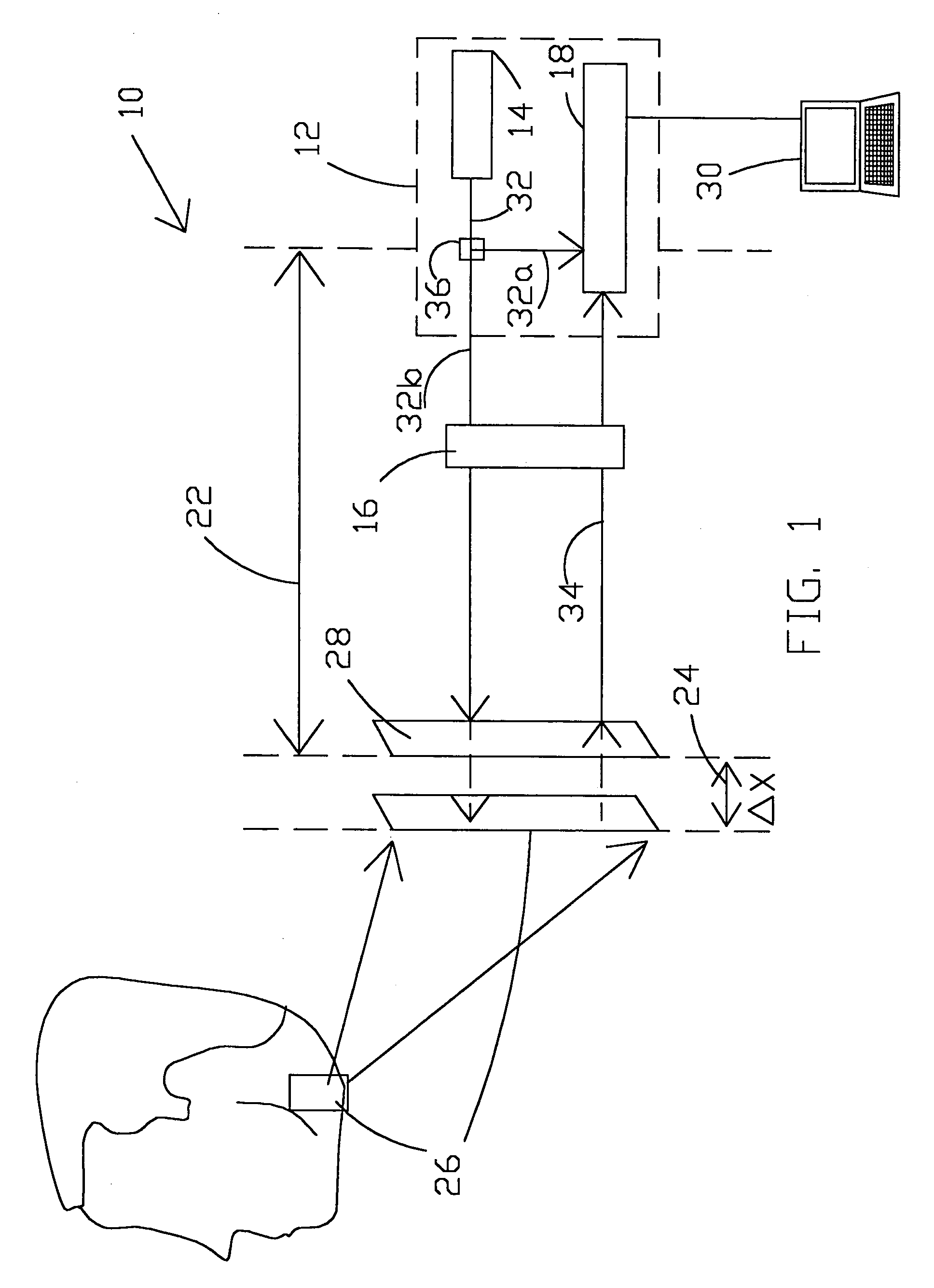
[0037]The present invention provides a non-contact method and apparatus for continuously monitoring physiological events such as the anatomical blood pressure waveform with sufficient accuracy and precision to determine important timing related parameters such as, for example, the left ventricular ejection time (LVET) and pre-ejection period (PEP). For cardiac cyclic timing diagnostic purposes, the timing of the blood pressure waveforms should be measured with sufficient accuracy so that the components of the waveform, e.g., the dicrotic notch, are available for accurate analysis. However, it has been observed by the inventors that cardiac cyclic analysis of the blood pressure waveform does not require absolute values of blood pressure. Thus, while the present technique does not necessarily directly measure or provide absolute values of blood pressure, cyclic analysis of the blood pressure waveform can be readily performed utilizing the data produced by the present invention. Calibr...


PUM


Abstract

A non-contact method and apparatus for continuously monitoring a physiological event in a human or animal, such as blood pressure, which involves utilizing a laser-based interferometer system to produce a waveform that is representative of continuous blood pressure in a subject. The invention may preferably utilize a laser Doppler vibrometer which is oriented to produce a laser beam directed toward the subject substantially perpendicular to a skin surface of the subject wherein the skin surface is moveable in response to blood pressure. The vibrometer is sensitive to motion of the skin surface in a direction parallel to the laser beam and produces a signal representative of this motion. By plotting the velocity of the skin surface movement in the direction parallel to the laser beam with respect to time, a waveform is produced that has been found to be representative of the blood pressure waveform and highly defined to thereby permit accurate timing analysis thereof relating to cardiac cycles.

Description

STATEMENT OF GOVERNMENT INTEREST[0001]The invention described herein may be manufactured and used by or for the Government of the United States of America for governmental purposes without the payment of any royalties thereon or therefore.CROSS REFERENCE TO OTHER PATENT APPLICATIONS[0002]Not applicable.BACKGROUND OF THE INVENTION[0003](1) Field of the Invention[0004]The present invention relates generally to a method and apparatus for measuring and monitoring physiological events in humans and animals, and more particularly to a non-contact method and apparatus for continuously measuring and monitoring physiological events in humans or animals using a laser Doppler vibrometer to create waveforms which are directly related to the physiological events.[0005](2) Description of the Prior Art[0006]For decades, there has been a long felt but unsolved need to continuously and accurately measure physiological events such as blood pressure without making contact with the patient. For many pa...

Claims


Application Information

Patent Timeline
IPC IPC(8): A61B5/00
CPCA61B5/021A61B5/113A61B5/0059A61B5/0816A61B5/02108
Inventor ANTONELLI, LYNN T.LOMBA, JOHN F.OHLEY, WILLIAM J.
Owner THE UNITED STATES OF AMERICA AS REPRESENTED BY THE SECRETARY OF THE NAVY
Why Eureka
Try Eureka