Bone plating system

a technology of bone plate and screw, applied in the field of bone plate plating system, can solve the problems of peri-articular fractures, peri-articular fractures, and peri-articular fractures, and achieve the effects of improving clinical outcomes, improving treatment efficiency, and improving clinical outcomes

Inactive Publication Date: 2006-10-31
DEPUY SYNTHES PROD INC
View PDF77 Cites 296 Cited by
  • Summary
  • Abstract
  • Description
  • Claims
  • Application Information

AI Technical Summary

Benefits of technology

[0012]In one embodiment, the bone plate has a trapezoidal shaped cross section in regions between the first and second plate holes for minimizing contact between bone and the bone-contacting surface. Additionally, at least one of the second plate holes is longitudinally elongated and has an edge inclined at an angle to the upper surface toward the bone-contacting surface for displacing the bone plate when engaged by the head of a second bone screw.

Problems solved by technology

However, treatment of certain fractures, such as peri-articular fractures, which require a fixed angular relationship between the bone plate and screws, remains problematic.
Although these conventional systems are particularly well-suited to promoting healing of the fracture by compressing the fracture ends together and drawing the bone into close apposition with other fragments and the bone plate, the angular relationships between the plate and screws are not fixed and can change postoperatively.
This can lead to mal-alignment and poor clinical results.
The compression results in high strain in the bone, and, consequently, energy storage.
With the dynamic loading resulting from physiological conditions, loosening of the plate and screw and loss of the stored energy can result.
However, locking screws have a limited capability to compress bone fragments.
Locking screws have a high resistance to shear force that ensure stability at the bone screw / plate hole interface, but possess a limited ability to compress bone fragments.
Thus, the long term benefits of combining non-locking screws with locking screws are not obtained.
Because the plate holes are only partially threaded, the locking screws used may not be able to maintain the fixed angular relationship between the screws and plate under physiological loads.
This can result in loss of fixation or loss of established intraoperative plate orientation.
Additionally, because of the plate hole geometry, translation of the plate with the non-locking screws is limited to one direction only.
This may be a disadvantage in reduction and manipulation of fragments.

Method used


Image

  • Bone plating system
  • Bone plating system
  • Bone plating system

Examples


Embodiment Construction

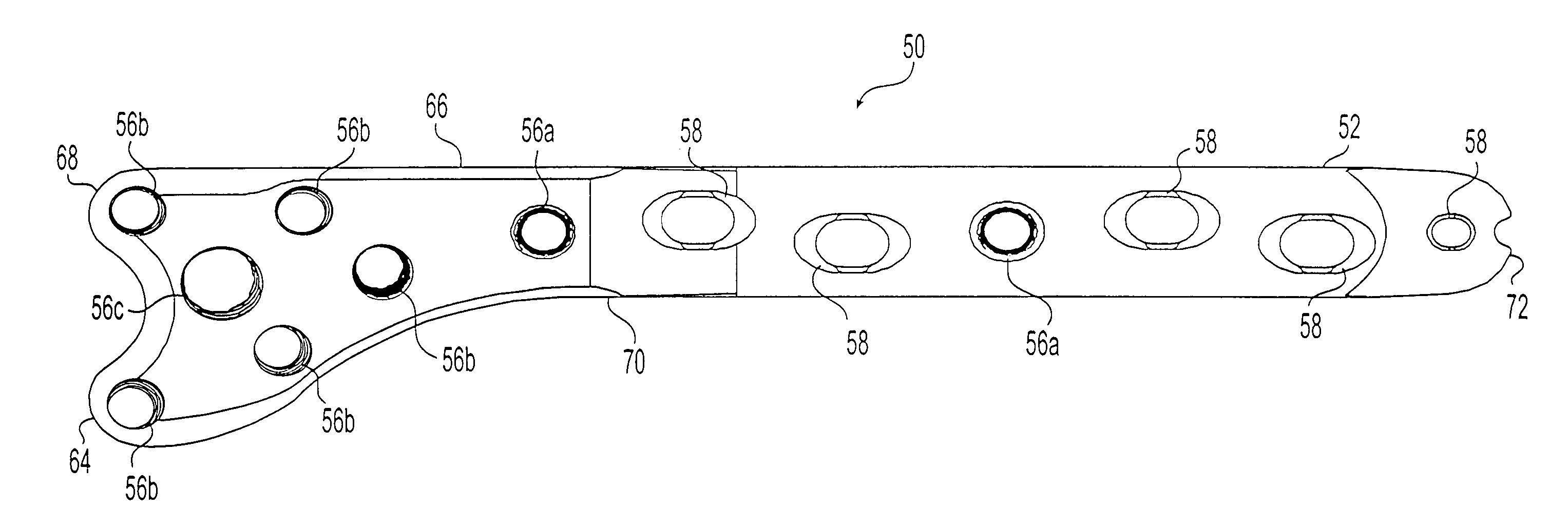
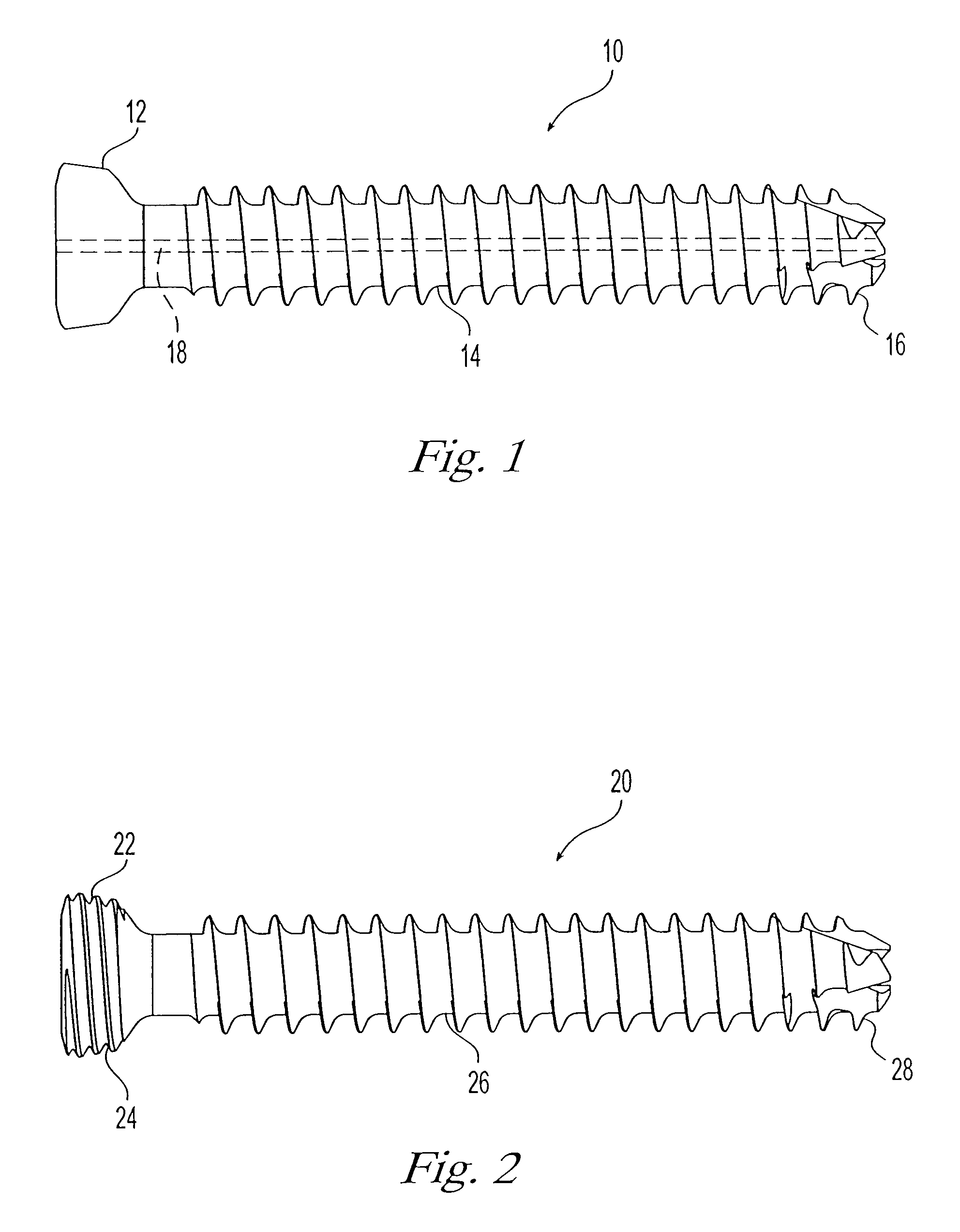
[0041]The bone plating system according to the present invention includes a bone plate, non-locking screws, and locking screws. FIG. 1 shows an example of a non-locking screw 10 that can be used with the present invention. In general and as described in more detail below, any surgical screw that has a non-threaded head 12 of an appropriate size and geometry for select plate holes of the bone plate can be used. Non-locking screw 10 has a shaft 14 that is at least partially threaded for attachment to bone. The length of shaft 14 and the shaft thread configuration can be selected for the particular application. As is well known in the art, the threads and a tip 16 can be made to be self-tapping and / or self-drilling to facilitate implantation. Shaft 14 can also be cannulated with a channel for receiving a guide wire to aid in proper placement.

[0042]FIG. 2 shows an example of a locking screw 20 that can be used with the present invention. In general and as described in more detail below,...


PUM


Abstract

The present invention relates to a bone plating system and method for fracture fixation of bone. The bone plating system includes a bone plate, at least one locking screw, and at least one non-locking screw. The bone plate has locking holes with threads and non-locking holes. The locking screws have a shaft with a thread for engaging bone and a head with a thread configured and dimensioned to mate with the thread of the locking holes. The non-locking screws have a thread for engaging bone and a non-threaded head. Both the locking and non-locking screws remain seated in their respective holes for substantially as long as the bone plate is implanted. The non-locking screws compress the bone plate against the bone and hold fracture reduction while the locking screws are secured to the plate at a fixed angular relationship. The mixed fixation achieved by this bone plating system and method is particularly useful for treatment of per-articular fractures.

Description

CROSS-REFERENCE TO RELATED APPLICATIONS[0001]This application is a continuation of U.S. patent application Ser. No. 09 / 660,287, filed on Sep. 12, 2000 now U.S. Pat. No. 6,626,486, which claims the benefit under 35 U.S.C. § 119(e) of U.S. Provisional Application No. 60 / 153,239, filed on Sep. 13, 1999.FIELD OF THE INVENTION[0002]The present invention is directed to a bone plating system for fracture fixation, and in particular to a system including a bone plate having plate holes for both locking and non-locking screws.BACKGROUND OF THE INVENTION[0003]The clinical success of plate and screw systems for internal fixation of fractures is well-documented. However, treatment of certain fractures, such as peri-articular fractures, which require a fixed angular relationship between the bone plate and screws, remains problematic. Fixed angle devices for treatment of these fractures are available and include the Dynamic Condylar Screw System commercially available from Synthes (USA) of Paoli,...

Claims


Application Information

Patent Timeline
Patent Type & Authority Patents(United States)
IPC IPC(8): A61B17/58A61B17/80
CPCA61B17/8057A61B17/8061A61B17/80Y10S606/902A61B17/8625
Inventor WEAVER, PAUL C.MAST, JEFF W.MAYO, KEITH A.BOLHOFNER, BRETT R.LITTLE, DAVID
Owner DEPUY SYNTHES PROD INC
Why Eureka
Try Eureka