Color picture tube apparatus

a tube apparatus and tube tube technology, applied in the direction of electric discharge tubes, contacts, snap-action arrangements, etc., can solve the problems of limiting the degree of freedom in the winding arrangement, the slot core cannot be sufficiently satisfied, and the degree of freedom cannot be maintained. , to achieve the effect of reducing the deflection power, excellent quality and maintaining the degree of freedom

Inactive Publication Date: 2006-10-31
MATSUSHITA TOSHIBA PICTURE DISPLAY CO LTD
View PDF5 Cites 2 Cited by
  • Summary
  • Abstract
  • Description
  • Claims
  • Application Information

AI Technical Summary

Benefits of technology

[0008]The present invention has been achieved in order to solve the above-mentioned problem in the prior art, and its object is to provide an energy-efficient color picture tube apparatus of very excellent quality, including a deflection yoke capable of further reducing a deflection power while maintaining the degree of freedom in a winding arrangement of coils.

Problems solved by technology

Thus, there is a limit to the degree of freedom in a winding arrangement.
However, the slot core shown in FIG. 8 cannot sufficiently satisfy the recent request for further reducing a deflection power.

Method used


Image

  • Color picture tube apparatus
  • Color picture tube apparatus
  • Color picture tube apparatus

Examples


Embodiment Construction

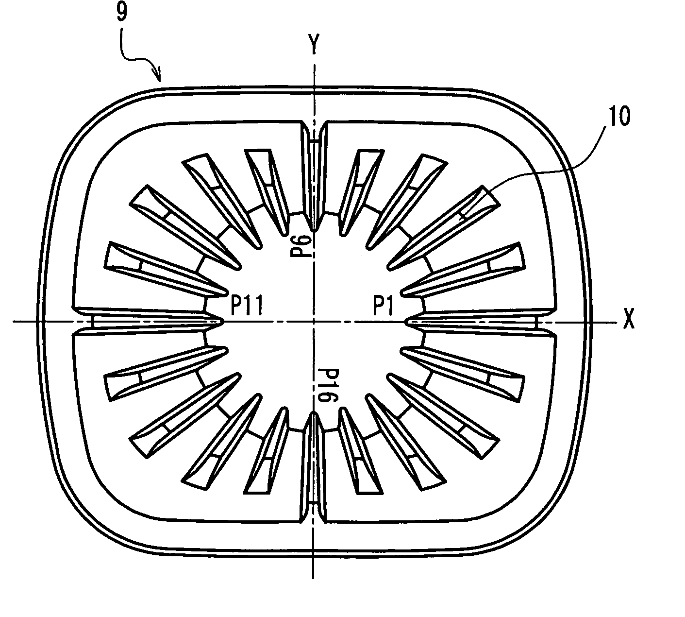
[0022]In the color picture tube of the present invention, the lengths in the tube axis direction of at least the horizontal axial convex portions or the vertical axial convex portions are larger than those of the diagonal convex portions. Therefore, a deflection power can be reduced while the degree of freedom in a winding arrangement of the horizontal deflection coil and the vertical deflection coil is secured. Thus, the windings of the horizontal deflection coil and the vertical deflection coil can be arranged so as to provide a desired deflection magnetic field distribution, so that an energy-efficient color picture tube of very excellent quality can be provided.

[0023]Hereinafter, the present invention will be described by way of specific numerical examples. However, the following numerical examples are shown merely for illustrative purposes, and the present invention is not limited thereto.

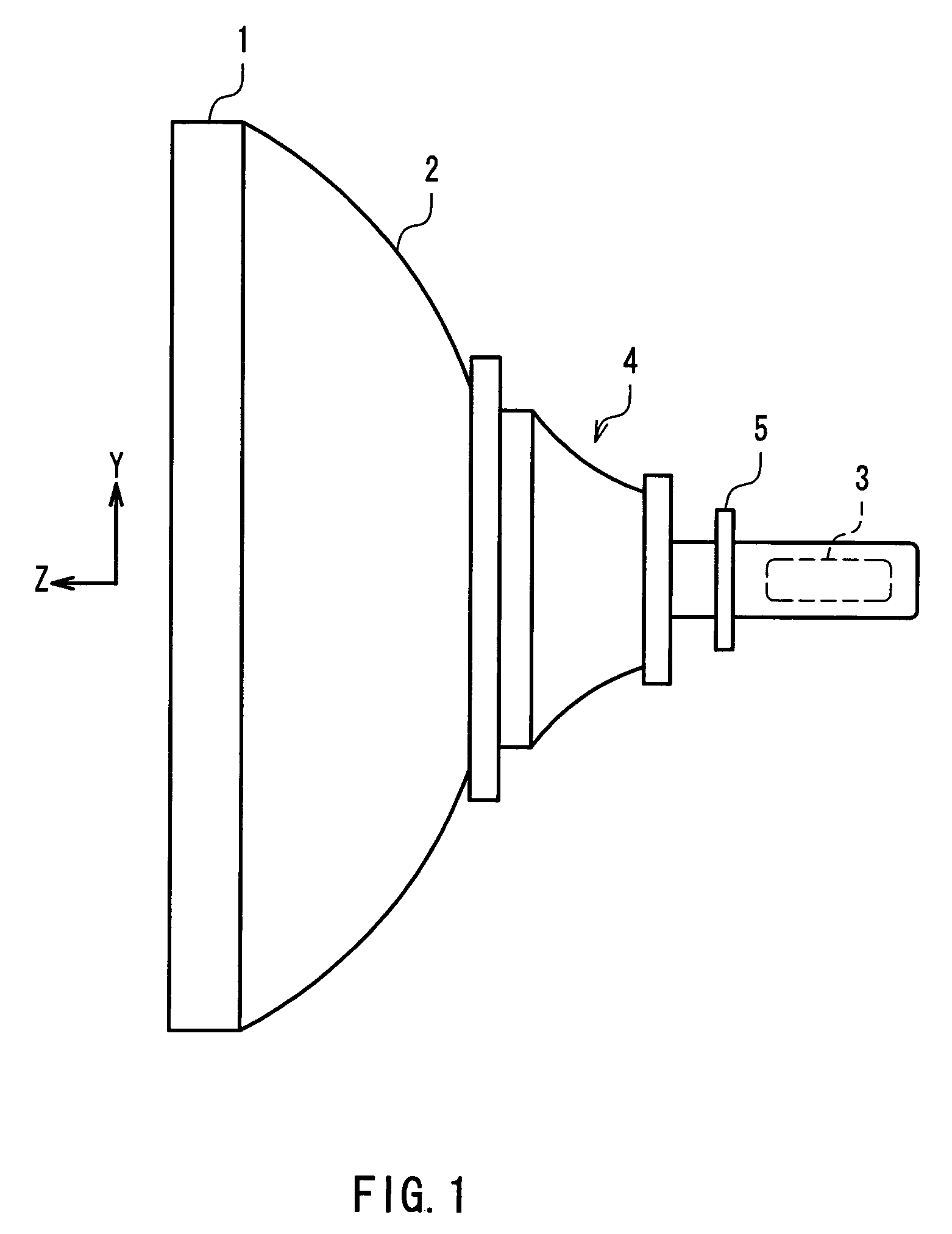
[0024]FIG. 1 is a view showing an outer appearance of a color picture tube apparatus to wh...


PUM


Abstract

A ferrite core constituting a deflection yoke includes a plurality of convex portions in a ridge shape on an inner surface thereof. Among the plurality of convex portions, assuming that the convex portions in a range excluding a range of −20° to +20° with respect to a horizontal axis and a range of −20° to +20° with respect to a vertical axis are diagonal convex portions, the lengths in a tube axis direction of at least horizontal axial convex portions on a horizontal axis or vertical axial convex portions on a vertical axis are larger than those of the diagonal convex portions. Because of this, a color picture tube apparatus with a deflection power reduced can be provided while the degree of freedom in a winding arrangement of deflection coils is secured.

Description

BACKGROUND OF THE INVENTION[0001]1. Field of the Invention[0002]The present invention relates to a color picture tube apparatus used in a television, a computer display, or the like.[0003]2. Description of the Related Art[0004]In order to reduce a deflection power and suppress the heat generated by a deflection yoke, JP61(1986)-56757U discloses a so-called slot core in which a plurality of convex portions protruding toward a tube axis of a picture tube are provided on an inner surface of a ferrite core constituting a deflection yoke. FIG. 7 shows a cross-sectional view of the deflection yoke with the slot core, taken along a surface vertical to the tube axis at a position close to an electron gun. Reference numeral 9 denotes a ferrite core, and 10 denotes a plurality of convex portions provided on an inner surface of the ferrite core 9. Windings are inserted in grooves between the convex portions 10 adjacent to each other in a circumferential direction, whereby a vertical deflection...

Claims


Application Information

Patent Timeline
Patent Type & Authority Patents(United States)
IPC IPC(8): H01J29/70H01J29/76
CPCH01J29/76H01J2229/7031H01J2229/7032
Inventor TAGAMI, ETSUJI
Owner MATSUSHITA TOSHIBA PICTURE DISPLAY CO LTD
Why Eureka
Try Eureka