Device for calibrating the frequency of an oscillator, phase looked loop circuit comprising said calibration device and related frequency calibration method

a technology of oscillator and calibration device, which is applied in the direction of frequency analysis, generator stabilization, pulse automatic control, etc., can solve the problem of increasing the convergence time of the calibration method by a large bit number, and achieve the effect of small convergence tim

Active Publication Date: 2006-10-31
STMICROELECTRONICS SRL
View PDF7 Cites 60 Cited by
  • Summary
  • Abstract
  • Description
  • Claims
  • Application Information

AI Technical Summary

Benefits of technology

[0014]Still in accordance with the present invention it is possible to provide a method for calibrating the frequency of an oscillator of a phase looked loop circuit.
[0015]Thanks to the present invention it is possible to provide a device for calibrating a frequency of an oscillator which allows the use of a VCO having a reduced voltage / frequency gain and a reduced input voltage level as required by the present radio communication systems.

Problems solved by technology

The precision of the frequency calibration in this device is due to the bit number of the digital signal; however the use of a digital signal with a large bit number increases the convergence time of the calibration method.

Method used


Image

  • Device for calibrating the frequency of an oscillator, phase looked loop circuit comprising said calibration device and related frequency calibration method
  • Device for calibrating the frequency of an oscillator, phase looked loop circuit comprising said calibration device and related frequency calibration method
  • Device for calibrating the frequency of an oscillator, phase looked loop circuit comprising said calibration device and related frequency calibration method

Examples


Embodiment Construction

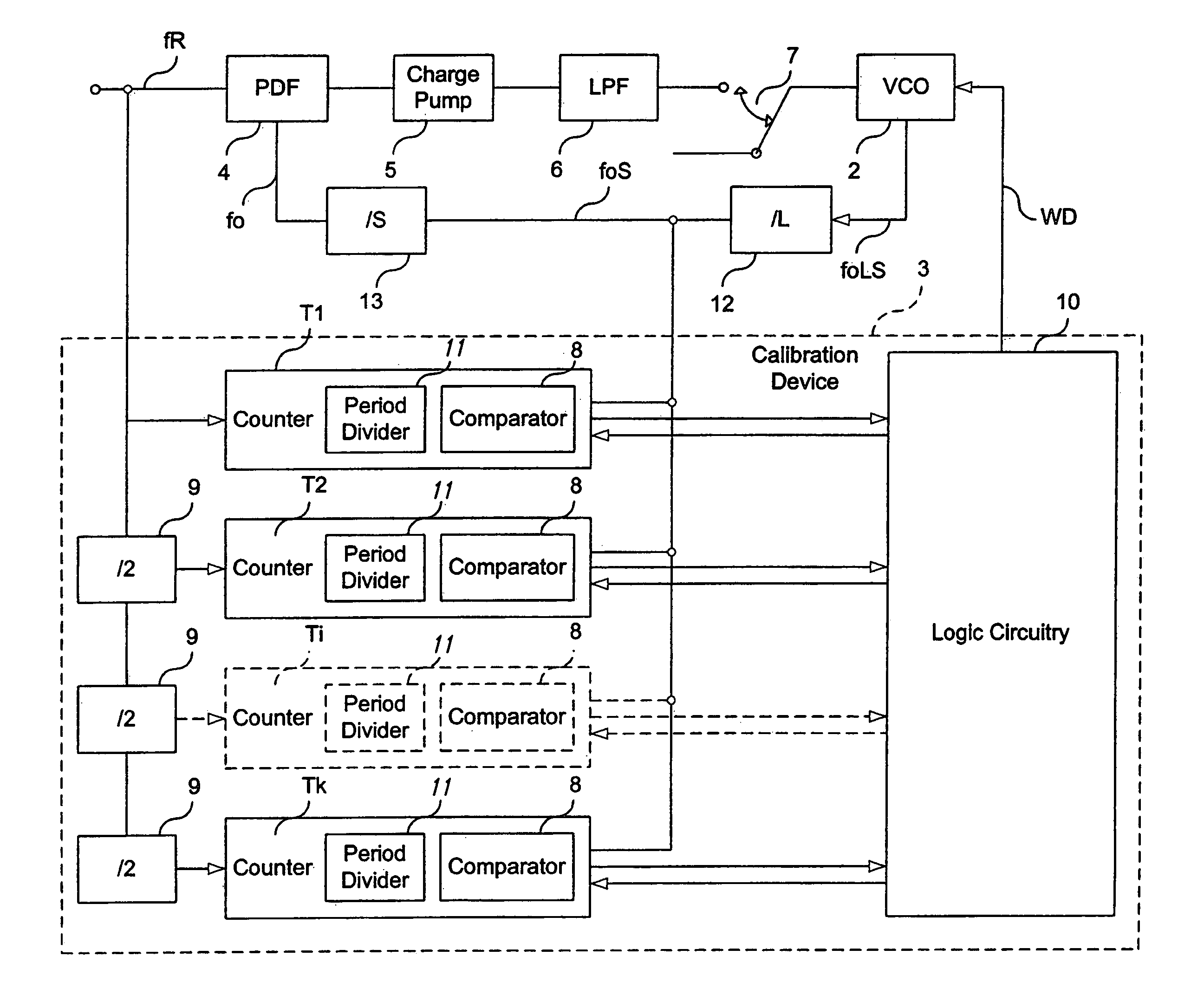
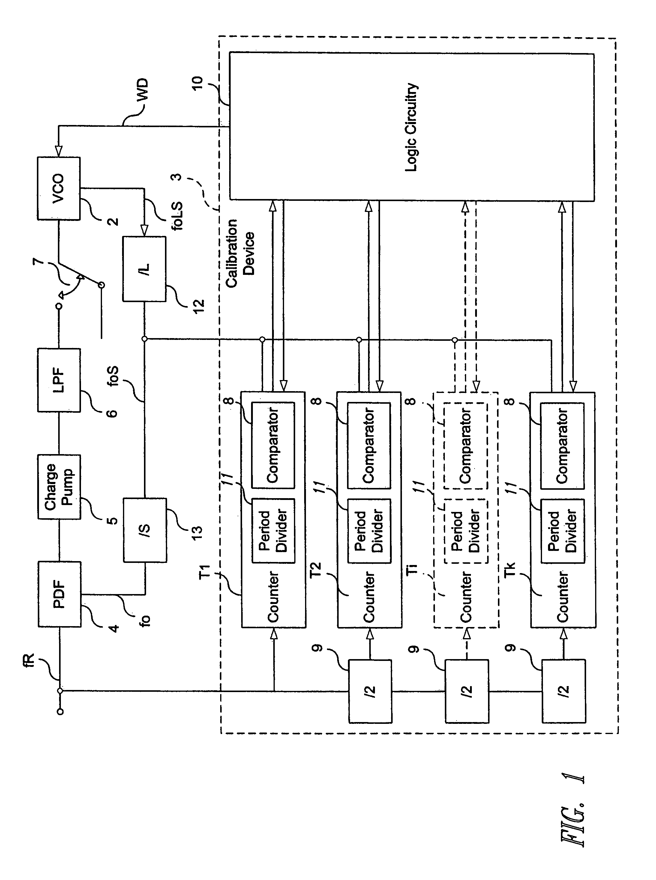
[0019]With reference to FIG. 1 a phase-locked loop (PLL) 1 comprising a voltage-controlled oscillator (VCO) 2 and a device 3 for calibrating the frequency of the VCO 2 are shown. The PLL comprises a phase detector (PDF) 4 adapted to detect the phase difference between the input reference frequency fR and the frequency fo. The output voltage signal of the PDF 4 is sent to a charge pump 5 having an output signal that is filtered by a low-pass filter (LPF) 6. The VCO 2 can have as input voltage level either a reference voltage Vref or the output voltage signal of the filter LPF 6; in fact there is a switch 7 that can be connected with the reference voltage Vref or with the output voltage signal of the filter LPF.

[0020]The VCO 2 has an oscillating frequency given by L*S*fo that is calibrated by an output digital signal WD of the device 3.

[0021]The device 3 comprises at least one counter Ti having a first input frequency proportional to a reference frequency fR and a second input frequen...


PUM


Abstract

A device calibrates the frequency of an oscillator. The oscillator has first and second inputs and generates an output frequency responsive to a first voltage signal at the first input. The calibration device generates a calibration signal applied at the second input of the oscillator for calibrating its output frequency and comprises a counter. The counter has a first input frequency proportional to a reference frequency and a second input frequency proportional to the output frequency. The counter counts the time window number given by the ratio of the second to first frequencies. The device comprises a comparator that compares the counted time window number with a prefixed time window number. The calibration device changes the value of the calibration signal if the counted time window number is different from the prefixed time window number and until the counted time window number is equal to the prefixed time window number.

Description

BACKGROUND OF THE INVENTION [0001]1. Field of the Invention[0002]The present invention refers to a device for calibrating the frequency of an oscillator, to a phase looked loop circuit comprising said calibration device and to the related frequency calibration method.[0003]2. Description of the Related Art[0004]In the present radio communication systems phase looked loop circuits (PLL) are generally utilized for generating oscillating electric signals. Generally the PLLs comprise a voltage controlled oscillator (VCO) generation an oscillating output signal as a response of a voltage level applied at the input. The specific parameters of the voltage / frequency relationship depend on the parameters of the VCO manufacturing process, the values of the electric components that it comprises, the ambient temperature and the other factors.[0005]For reducing the effects of the temperature variations and of the process parameters, devices for calibrating the frequency of the VCO are presently ...

Claims


Application Information

Patent Timeline
Patent Type & Authority Patents(United States)
IPC IPC(8): H03L7/00H03L1/02H03L7/099H03L7/10H03L7/12H03L7/191
CPCH03L7/099H03L7/10H03L7/191H03L2207/06
Inventor GRAMEGNA, GIUSEPPE
Owner STMICROELECTRONICS SRL
Why Eureka
Try Eureka