Triple-band bend tolerant optical waveguide

a technology of optical waveguides and bend-tolerant optical fibers, applied in the field of optical waveguides, can solve the problems of inability to adjust the mfd of the two fiber ends, loss of light radiated out of the core into the cladding of the fiber, and loss of light radiated out of the core into the fiber, etc., and achieve the effect of minimising splice loss

Active Publication Date: 2006-10-31
CORNING RES & DEV CORP
View PDF31 Cites 242 Cited by
  • Summary
  • Abstract
  • Description
  • Claims
  • Application Information

AI Technical Summary

Benefits of technology

[0038]Fibers in accordance with embodiments of the present invention provide tight bend tolerance designs, which allows them to be either fusion spliced or mechanically connected to other high MFD fibers with minimal splice losses.

Problems solved by technology

For such connectors, it is not practical to adjust the MFD of the two fiber ends (for duplex applications) by high temperature diffusion of core dopants, as can be done when fusion splicing two optical fibers for long haul cables (see, e.g., EP 1094346 A1).
Macrobending loss occurs when a length of fiber is bent into a curve such that some light is radiated out of the core into the cladding of the fiber and lost.
Microbending losses result from concentrated pressure or stresses exerted on the surface of the fiber.
When the outer surface of the fiber is pressed against the raised points, a coating that is too hard may transfer these stresses to the core, causing scattering losses.
The stripped fiber ends are then susceptible to breakage from abrasion and moisture.
Although these fibers provide low bend loss, their small MFDs make them unsuitable for connectorization to the low cost, large (>8.0 microns) MFD telecom fibers.
Multi-wavelength versions of these fibers have the smallest MFDs and therefore the largest MFD mismatches and associated connector losses making them impractical for premise applications.
These fibers can only be fusion spliced or thermally treated to eliminate the MFD mismatch, which are not practical procedures for the multiple plug-in / disconnect applications.

Method used


Image

  • Triple-band bend tolerant optical waveguide
  • Triple-band bend tolerant optical waveguide
  • Triple-band bend tolerant optical waveguide

Examples


example 1

[0068]One exemplary embodiment of an optical fiber in accordance with the present invention has the following material composition:

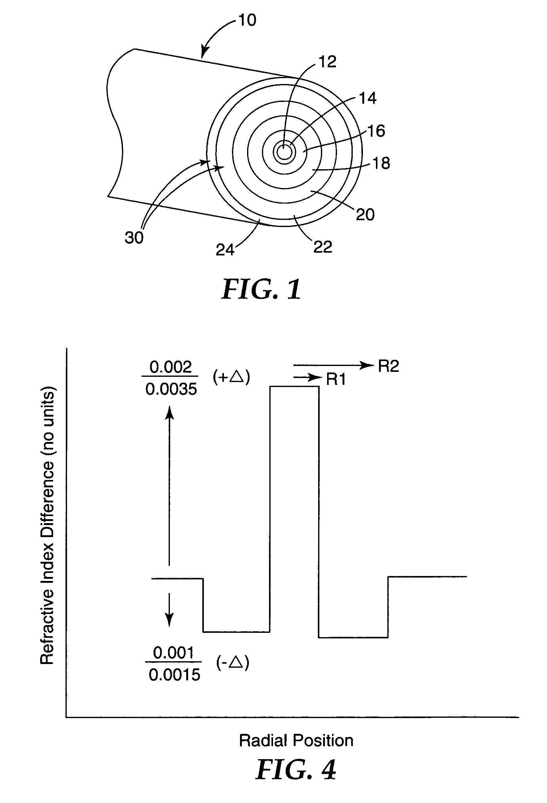
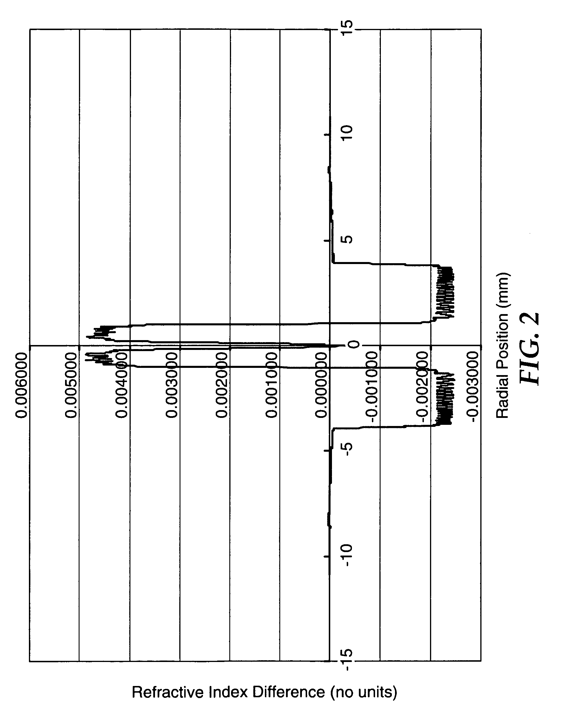
[0069]A preform having the material composition described above was manufactured using the modified chemical deposition (MCVD) process using a 19×25 mm fused silica tube by first depositing 20 cladding layers with flows of 412, 40 and 19 standard cc / min of SiCl4, POCl3, and SiF4, respectively. This was followed by 7 core layers consisting of 96 and 90 standard cc / min of SiCl4 and GeCl4, respectively, followed by two collapse passes and one seal pass resulting in a preform diameter of 17.8 mm. One or more overcollapses using 19×25 mm fused silica tubes may be required to obtain a final preform diameter of 23 mm. The refractive index profile of this preform prior to overcollapse is shown in FIG. 2. The preform was overcollapsed prior to drawing, and was drawn as an optical fiber.

[0070]In the present example, a hard, permanent polymer coating is placed on t...

example 2

[0085]A second sample of optical fiber having a similar design in accordance with the present invention was drawn and measured, with the following properties:

[0086]a.) clad / core radius ratio is 3.9

[0087]b.) +Δ of 0.0027

[0088]c.) −Δ of −0.0012

[0089]d.) ΔTot of 0.0039.

This design resulted in example fiber with the following properties:

[0090]Cutoff wavelength=1310 nm

[0091]MFD @ 1300 nm=8.1 microns

[0092]MFD @ 1550 nm=9.2 microns

[0093]Bend loss (10 mm radius)=0.02 dB / turn @ 1550 nm

[0094]Bend loss (10 mm radius)=0.08 dB / turn @ 1625 nm

[0095]Bend loss (10 mm radius)=0.12 dB / turn @ 1650 nm

[0096]Index delta values were taken from measurements done on the fiber preforms before fiber drawing. The measurements were done with a He—Ne laser at 633 nm. The refractive index of the outer cladding in these fibers is essentially the same as pure silica, which for calculation purposes was taken to be 1.458 at 633 nm.

example 3

[0097]The bend performance of an optical fiber in accordance with another embodiment of the present invention (SMGGP-TW) was compared with commercially available SMF-28™ fiber from Corning, with commercially available Volition™ single wavelength band fiber (SMGGP-SW), and a dual wavelength band fiber (SMGGP-DW, as described in commonly-owned, currently pending U.S. patent application Ser. No. 10 / 172,093) from 3M Company, St. Paul, Minn. The results are shown in Table 1.

[0098]

TABLE 1Bend lossCutoffMFDMFD1550 nmRic / Cable1300 nm1550 nm1550 nm1625 nmdB 1 / 4+Δ−ΔΔTotRconmμmμmdB / turndB / turnturnCorning0.00350.00359.210.40.380.62.4SMF-28 ™SMGGP-SW0.00240.00249.210.411.63.3SMGGP-0.0020−0.00280.00482.69.010.00.61.20.12DWSMGGP-TW0.0025−0.00160.00413.48.69.40.10.30.05

[0099]In the above table, the bend loss measurements for columns 9 and 10 were measured using a 10 mm bend radius, and the bend loss measurements shown in column 11 (last column) were measured using a 6 mm bend radius (¼ turn). The t...


PUM


Abstract

An optical waveguide comprises a core, an inner cladding laterally surrounding the core, and an outer cladding laterally surrounding the inner cladding, wherein the core, inner cladding, and outer cladding have a depressed well configuration. The waveguide operates in three or more wavelength bands, wherein a first wavelength band is centered at about 1300 nm, and wherein a second wavelength band is centered at about 1625 nm. The waveguide has bend losses that are less than or equal to 1.0 dB / turn when measured on a 5 mm radius bend at 1625 nm and bend losses that are less than or equal to 1.5 dB / turn when measured on a 5 mm radius bend at 1650 nm.

Description

CROSS REFERENCE TO RELATED APPLICATION[0001]This application is a continuation in part of U.S. application Ser. No. 10 / 930,575, filed Aug. 31, 2004, incorporated by reference herein in its entirety.FIELD OF THE INVENTION[0002]The present invention relates to an optical waveguide operating in the 1300–1650 nm window. In particular, the present invention relates to a depressed well optical fiber having a triple wavelength band design that is able to operate in tight bend environments with minimal bend induced losses. Further, the optical fiber can have a mode field diameter (MFD) that closely matches large mode field diameter fibers such as common long haul telecommunications fibers.BACKGROUND OF THE INVENTION[0003]Optical fibers form some of the main lines through which telecommunications data is connected all over the world. An optical fiber typically includes a core region surrounded concentrically by a cladding. Some fiber designs, known as “double cladding” designs, surround the ...

Claims


Application Information

Patent Timeline
Patent Type & Authority Patents(United States)
IPC IPC(8): G02B6/02
CPCG02B6/02004G02B6/03627G02B6/02395G02B6/03611
Inventor WU, JUNJUNSYKORA, CRAIG R.
Owner CORNING RES & DEV CORP
Why Eureka
Try Eureka