Dual-band bend tolerant optical waveguide

a bend-tolerant, optical waveguide technology, applied in the direction of optical waveguide light guides, optical fibres with multi-layer cores/claddings, instruments, etc., can solve the problems of large splice losses, limited first fiber optic telecommunication systems, and inability to adjust the mfd of the two fiber ends by high temperature diffusion of core dopants. , to achieve the effect of tight bend tolerance and minimal splice losses

Inactive Publication Date: 2005-09-20
CORNING RES & DEV CORP
View PDF20 Cites 11 Cited by
  • Summary
  • Abstract
  • Description
  • Claims
  • Application Information

AI Technical Summary

Benefits of technology

[0024]Fibers in accordance with the present invention provide tight bend tolerance in high MFD (>9 micrometers at 1550 nm) des

Problems solved by technology

Typically, one of the largest costs in establishing a fiber optic system is burying or installing the cable.
The first fiber optic telecommunication systems were limited to “long haul” applications from one telephone company central office to another.
For such connectors, it is not practical to adjust the MFD of the two fiber ends by high temperature diffusion of core dopants, as can be done when fusion splicing two optical fibers for long haul cables (see, e.g., EP 1094346 A1).
Also, the induced bend in optical fiber ends used in the Volition™ VF-45 fiber optic connector can be a source of optical loss when standard single mode telecommunications fibers are used.
Macrobending loss occurs when a length of fiber is bent into a curve such that some light is radiated out of the core into the cladding of the fiber and lost.
Microbending losses result from concentrated pressure or stresses exerted on the surface of the fiber.
When the outer surface of the fiber is pressed against the raised points, a coating that is too hard may transfer these stresses to the core, causing scattering losses.
The stripped fiber ends are then susceptible to breakage from abrasion and moisture.
A limitation imposed by matching to SMF-28 is the resulting poor bend performance inherent in

Method used


Image

  • Dual-band bend tolerant optical waveguide
  • Dual-band bend tolerant optical waveguide
  • Dual-band bend tolerant optical waveguide

Examples


example 1

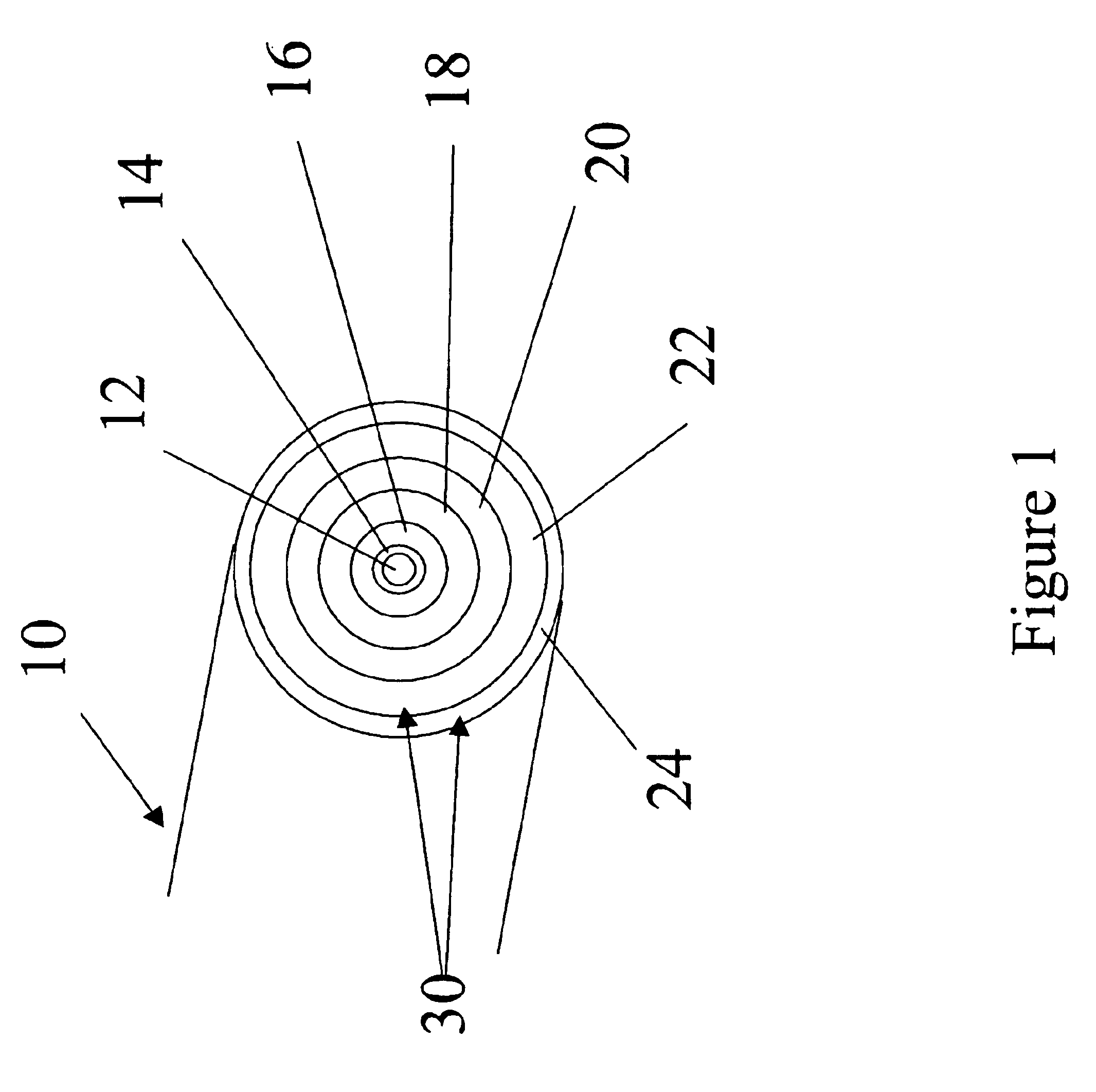
[0047]One exemplary embodiment of an optical fiber in accordance with the present invention has the following material composition:[0048]Core Low-lightly doped germanium silicate glass (2.5 mole % of GeO2)[0049]Inner cladding Phosphorus fluorosilicate (˜0.1 mole % P2O5 and 3.4 mole % F)[0050]Outer cladding Fused Silica (100 mole %)

[0051]A preform having the material composition described above was manufactured using the modified chemical deposition (MCVD) process using a 19×25 mm fused silica tube by first depositing 18 cladding layers with flows of 700, 100 and 110 standard cc / min of SiCl4, POCl3, and SiF4, respectively. This was followed by 10 core layers consisting of 164 and 92 standard cc / min of SiCl4 and GeCl4, respectively, followed by two collapse passes and one seal pass resulting in a preform diameter of 16.2 mm. Two overcollapses using 22×25 and 24×30 mm fused silica tubes were required to obtain a final preform diameter of 25.4 mm. This preform was then milled to a final...

example 2

[0066]A second sample of optical fiber having a similar design in accordance with the present invention was drawn and measured.

[0067]a.) clad / core diameter ratio is 2.4

[0068]b.) +Δ of 0.0014

[0069]c.) −Δ of −0.0028

[0070]d.) ΔTot of 0.0042

This design resulted in fiber with the following properties:

[0071]Cutoff wavelength=1225 nm

[0072]MFD @ 1300 nm=9.4 microns

[0073]MFD @ 1550 nm=10.4 microns

[0074]Bend loss (0.635 cm 90°)=<0.05 dB @ 1300 nm

[0075]Bend loss (0.635 cm 90°)=0.20 dB @ 1550 nm

[0076]Bend loss (0.635 cm 90°)=0.25 dB @ 1600 nm

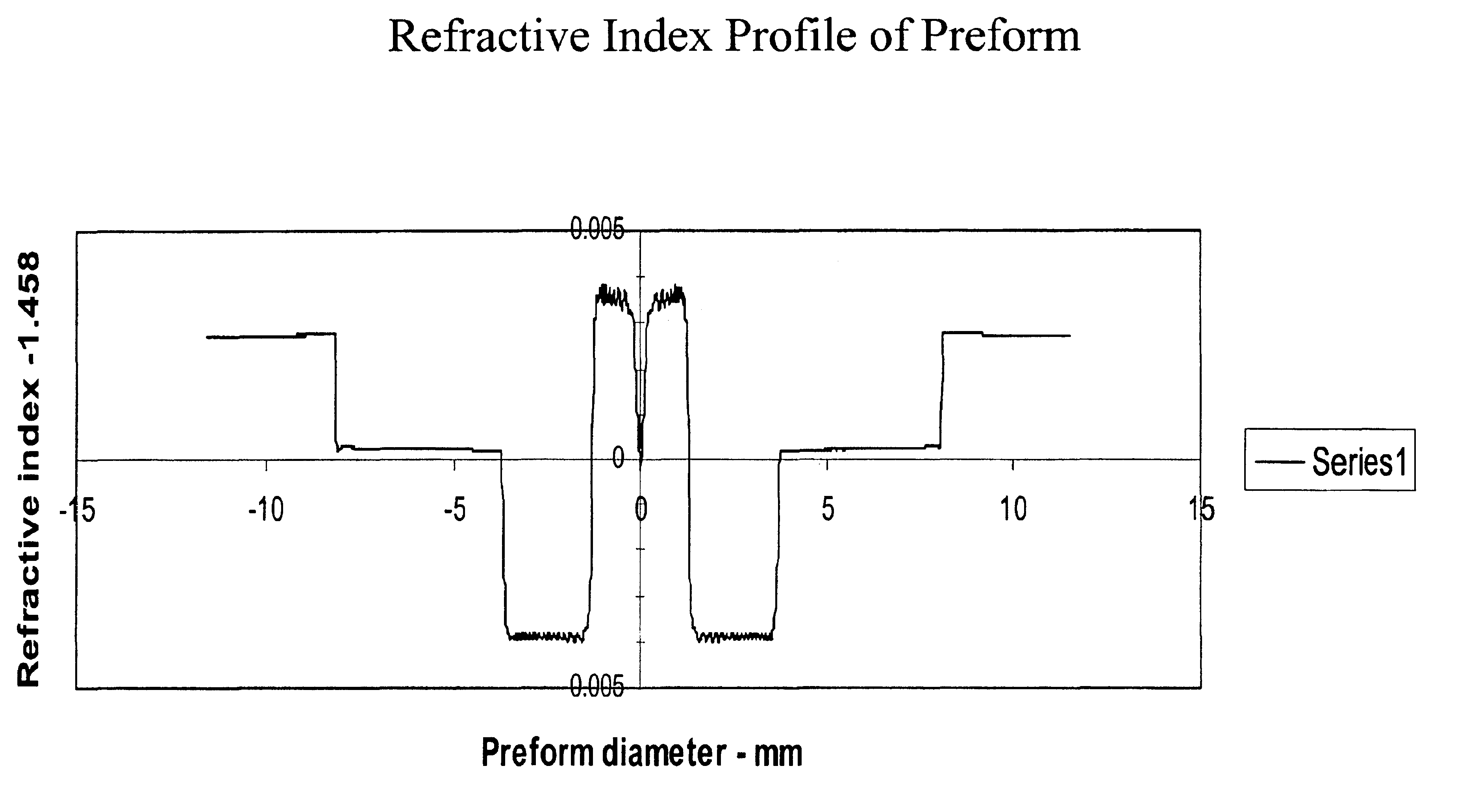
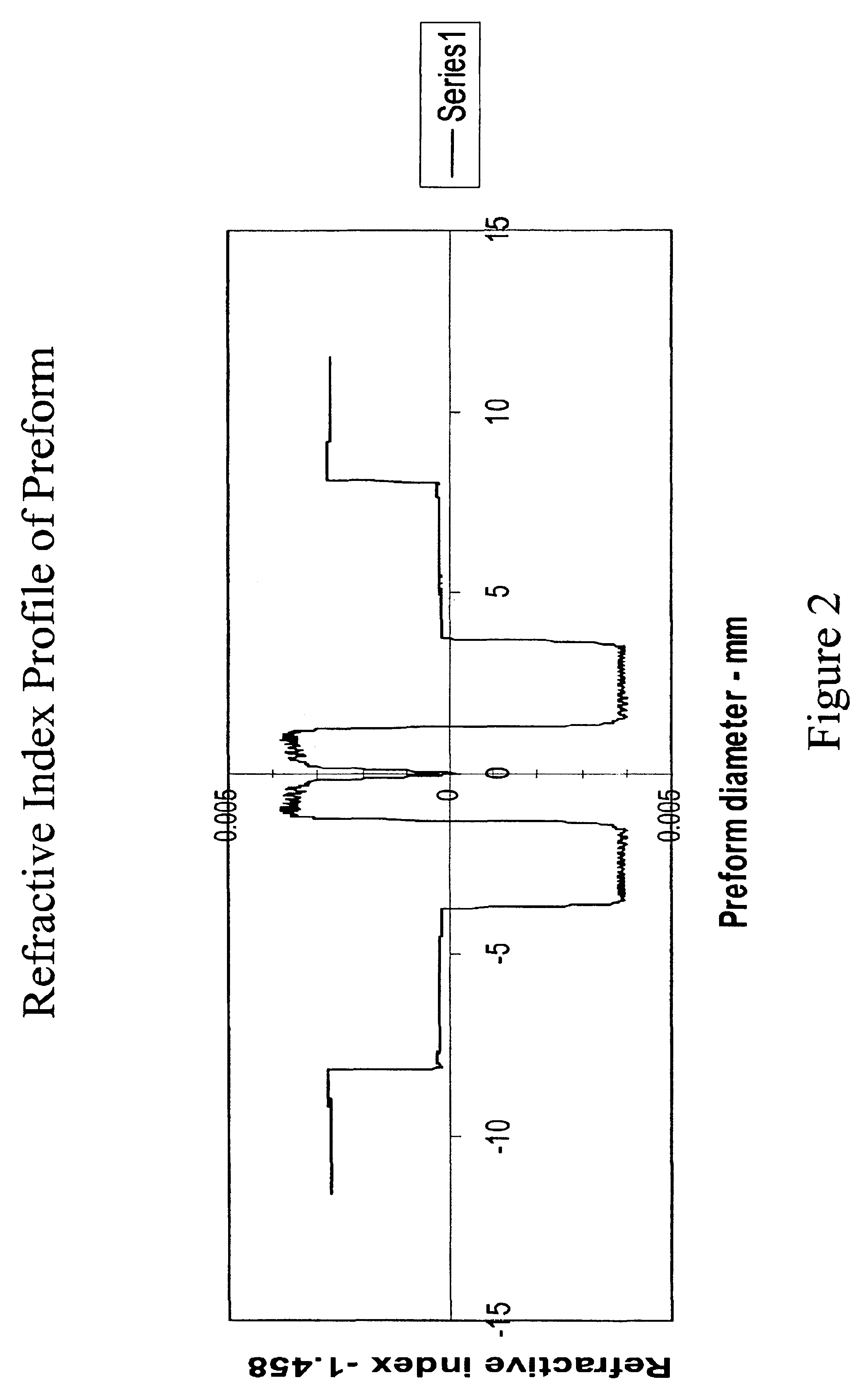
[0077]Index delta values were taken from measurements done on the fiber preforms before fiber drawing. The measurements were done with a He—Ne laser at 633 nm. The refractive index of the outer cladding in these fibers is essentially the same as pure silica, which for calculation purposes was taken to be 1.458 at 633 nm.

example 3

[0078]The bend performance of an optical fiber in accordance with the present invention was compared with two simple, single wavelength matched clad, matched mode-field diameter designs.

[0079]

Bend performanceBend performanceat 0.95 cm. (3 / 8″)at 0.95 cm. (3 / 8″)Bend performance at90° bend at 130090° bend at 15500.635 cm. (¼″) 90° bendFibernmnmat 1550 nm“Volition” type 0.7 dB3 dBTF 45 fiberN / A0.06 dB (cutoff 1500 nm)0.50 dB (cutoff 1400 nm)

[0080]As may be seen in the above table, a Volition™-type single mode fiber, available from 3M Company, St. Paul, Minn., was found to give adequate performance at a 0.95 cm (⅜″) radius 90 degree bend (henceforth referred to as a 0.95 cm (⅜″) 90 bend) when operating at 1300 nm, however, the bend loss increased to 0.7 dB at 1550 nm. At the 0.635 cm (¼″) 90 bend conditions, 1550 nm bend loss increased to 3 dB, which is equivalent to losing half the light intensity.

[0081]Test fiber 45 (called TF 45 fiber) is a mode matched, matched clad fiber in accordan...


PUM


Abstract

An optical waveguide, such as an optical fiber, including a core having a refractive index nco and a radius rco; an inner cladding laterally surrounding the core, the inner cladding having a refractive index nic and an outer radius of ric; an outer cladding laterally surrounding the inner cladding, the outer cladding having a refractive index noc; and a narrow depressed well, wherein nco>noc>nic. The range of the ratio of the inner, depressed-well clad radius, ric, to core radius, rco, varies from about 2.4 to 3.0. The waveguide has a +Δ of about 0.0014 to 0.0021, a −Δ of about −0.0021 to −0.0034, and a ΔTot of about 0.0043 to 0.0049.

Description

FIELD OF THE INVENTION[0001]The present invention relates to a depressed well optical waveguide operating in the 1300-1620 nm window. In particular, the present invention relates to a single mode fiber dual wavelength band design that is able to operate in tight bend environments with minimal bend induced losses while having a mode field diameter (MFD) that matches large mode-field diameter fibers such as common long haul telecommunications fibers.BACKGROUND OF THE INVENTION[0002]Optical fibers form some of the main lines through which telecommunications data is connected all over the world. An optical fiber typically includes a core region surrounded concentrically by a cladding. Some fiber designs, known as “double cladding” designs, surround the core region with an inner cladding, which is in turn surrounded by an outer cladding. The outer cladding likewise is surrounded by an external medium.[0003]The parameters in such double cladding waveguide designs usually are:[0004]Depende...

Claims


Application Information

Patent Timeline
IPC IPC(8): G02B6/036G02B6/02
CPCG02B6/03655G02B6/03605G02B6/02004G02B6/03611G02B6/028G02B6/02
Inventor VARNER, WAYNE FRANCISSYKORA, CRAIG RAYMOND
Owner CORNING RES & DEV CORP
Why Eureka
Try Eureka