Flow meter with magnetoresistive sensors and method of measuring flow

a flow meter and magnetoresistive technology, applied in the direction of instruments, liquid/fluent solid measurement, volume/mass flow by differential pressure, etc., can solve problems such as unbalance output related to bridges, and achieve the effect of eliminating potential decoupling

Active Publication Date: 2006-10-31
BADGER METER
View PDF12 Cites 17 Cited by
  • Summary
  • Abstract
  • Description
  • Claims
  • Application Information

AI Technical Summary

Benefits of technology

[0006]The flow meter disclosed herein utilizes an array of anisotropic magnetoresistive (AMR or MR) sensing elements adjacent to the path of travel of the magnet on the flow meter piston. An external follower and wiper are not required. This eliminates the potential for decoupling.

Problems solved by technology

The bridge has an unbalance output related to the angle of the field of the magnet with respect to the sensitive axis of the bridge.

Method used


Image

  • Flow meter with magnetoresistive sensors and method of measuring flow
  • Flow meter with magnetoresistive sensors and method of measuring flow
  • Flow meter with magnetoresistive sensors and method of measuring flow

Examples


Embodiment Construction

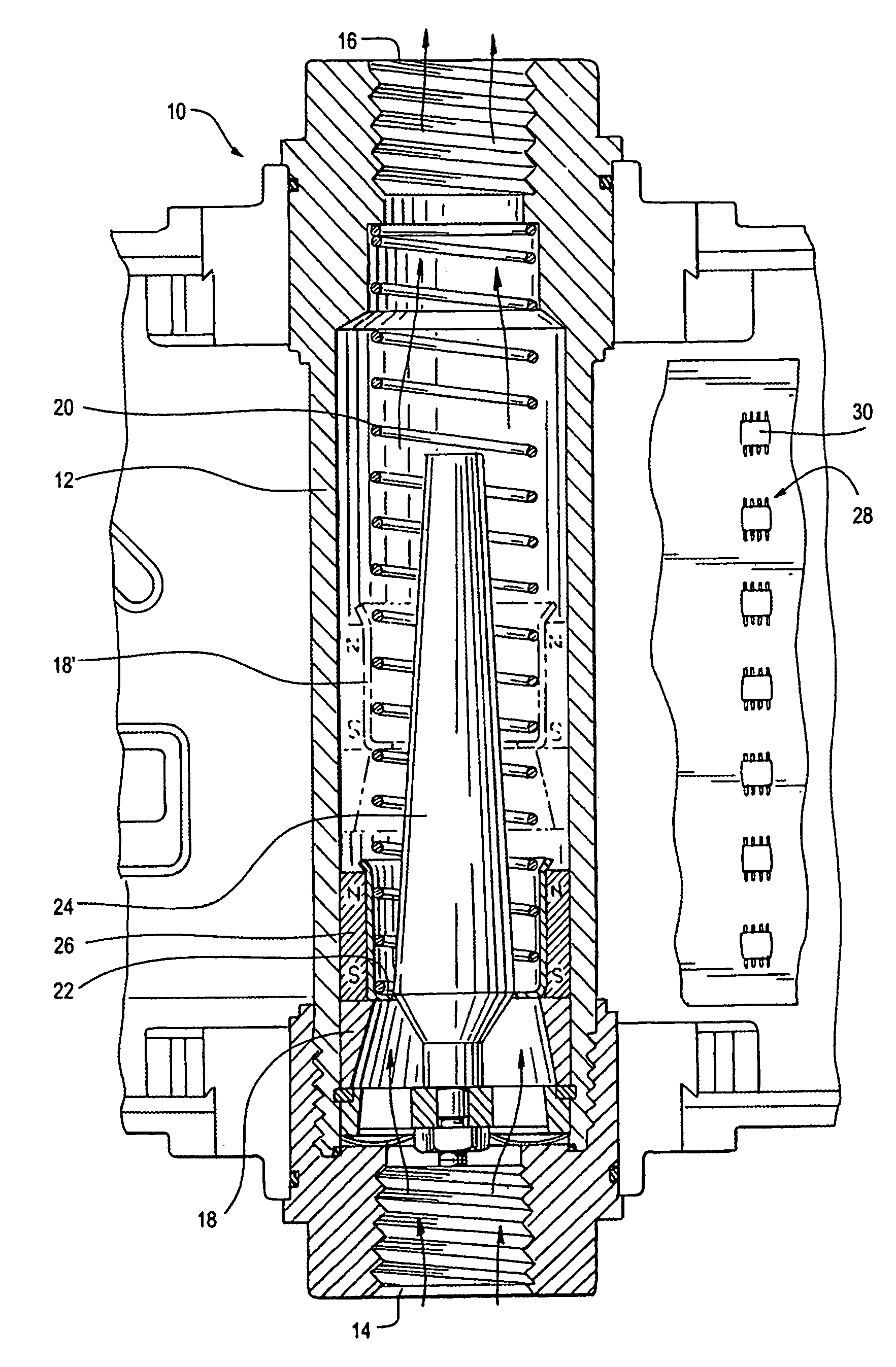
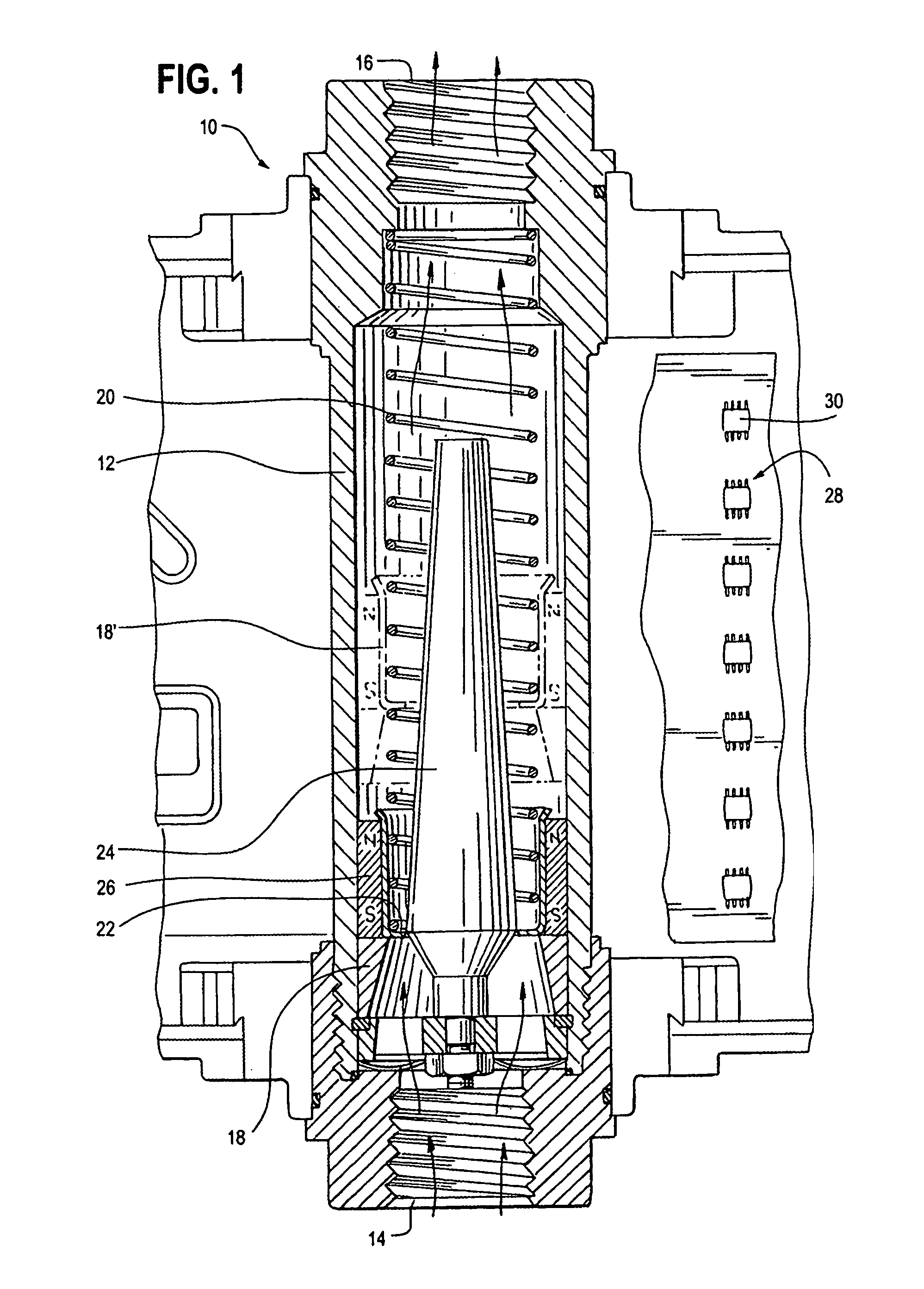
[0021]A variable area of flow meter 10, of the type shown in Hedland U.S. Pat. No. 3,805,611, is illustrated in FIG. 1. Cylindrical body 12, of a non-magnetic material, has an inlet 14 and an outlet 16. A piston 18 is biased toward the inlet by spring 20. The piston has a central opening 22 through which a conical plug 24 extends. Fluid flow through the body 12 creates a differential pressure across piston 18 which lifts the piston to a position at which the differential pressure balances the spring force as shown in broken lines at 18′. A magnet 26 is carried on piston 18 and has a field which extends outside cylindrical body 12. The position of magnet 26 and thus of the piston is sensed by an array 28 of MR sensors 30, providing signals from which flow rate of a fluid through the meter may be determined.

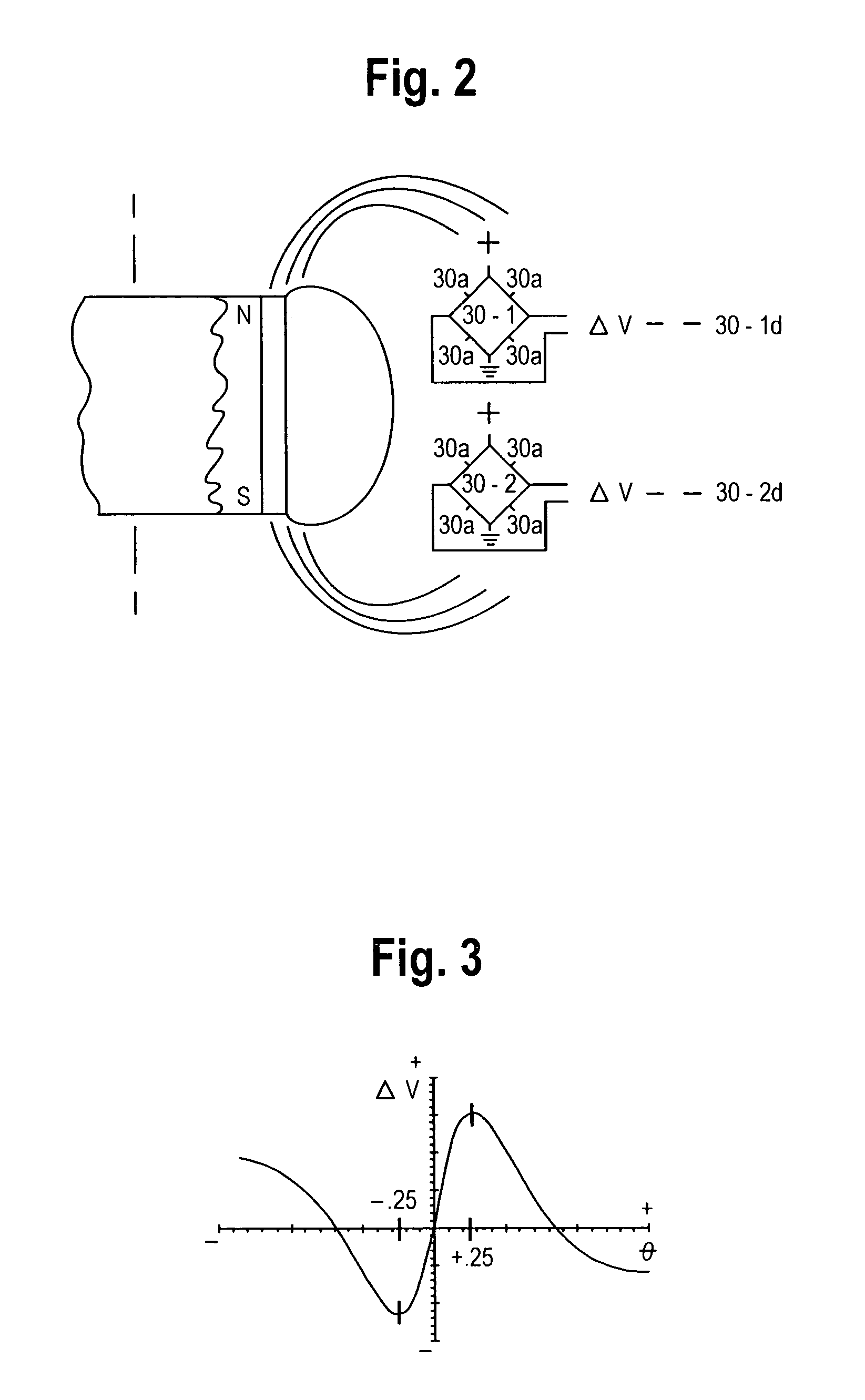
[0022]A preferred sensor 30 is a bridge circuit of four MR elements, as Honeywell type HMC 1501. Magnet 26 and two sensors 30-1, 30-2 are illustrated in FIG. 2. The four MR element...


PUM


Abstract

A variable area flow meter has a magnet carried by a piston which is moved to a position representing fluid flow. An array of magnetoresistive bridge sensors adjacent the path of magnet movement senses the magnet position. The bridges are unbalanced by the magnet field. The analog unbalance signals are read and processed in digital form to develop a flow signal. The flow meter circuits are powered from a 4–20 MA current loop or a remote power supply. Each bridge sensor is powered only when the bridge unbalance signal is being read, to minimize the power requirement.

Description

CROSS REFERENCE TO RELATED APPLICATIONS[0001]Not applicable.STATEMENT REGARDING FEDERALLY SPONSORED RESEARCH OR DEVELOPMENT[0002]Not applicable.REFERENCE TO SEQUENCE LISTING[0003]Not applicable.BACKGROUND OF THE INVENTION[0004]A variable area flow meter as shown in Hedland U.S. Pat. No. 3,805,611 typically has a cylindrical body with an inlet at one end and an outlet at the other. A piston inside the body is spring biased toward the inlet and is moved toward the outlet by fluid flow through the body. A conical plug extends through a hole in the end of the piston and is tapered toward the outlet. As the piston is moved against the spring by increased fluid flow, the opening for flow in the end of the piston grows larger. The piston reaches a stable position in the cylindrical body which is a measure of flow. If the cylindrical body is transparent, a scale on the body indicates the flow.[0005]Where the cylindrical body is not transparent, the Hedland '611 patent incorporates a magnet ...

Claims


Application Information

Patent Timeline
Patent Type & Authority Patents(United States)
IPC IPC(8): G01F1/24
CPCG01F1/24
Inventor STEVENS, ROBERT K.MCCLAIN, JONATHAN RAYLITTLE, RICHARD
Owner BADGER METER
Why Eureka
Try Eureka