
Optical disc drive apparatus

a technology of optical discs and drive cables, applied in the direction of instruments, data recording, track finding/aligning, etc., can solve the problems of further unlikely breakage of guide protruding cables, and achieve the effect of avoiding disc tray falling

Inactive Publication Date: 2006-10-31
FUNAI ELECTRIC CO LTD
View PDF9 Cites 11 Cited by
  • Summary
  • Abstract
  • Description
  • Claims
  • Application Information

AI Technical Summary

Benefits of technology

[0015]An object of the present invention is to provide an optical disc drive apparatus which is unlikely to be broken and can avoid falling of the disc tray even if a force in a transversal direction is applied to the disc tray while it is at a disc-removable position.
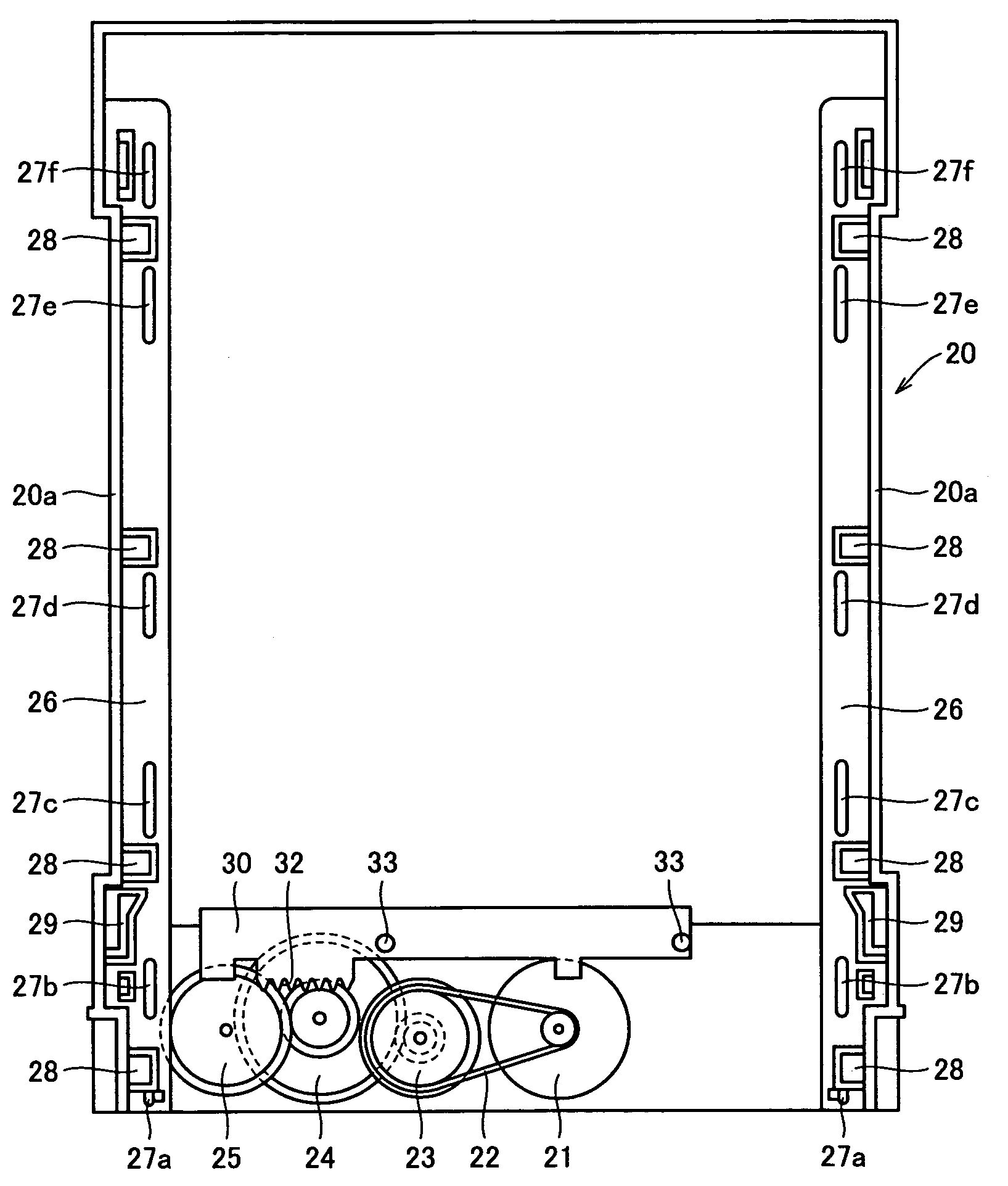
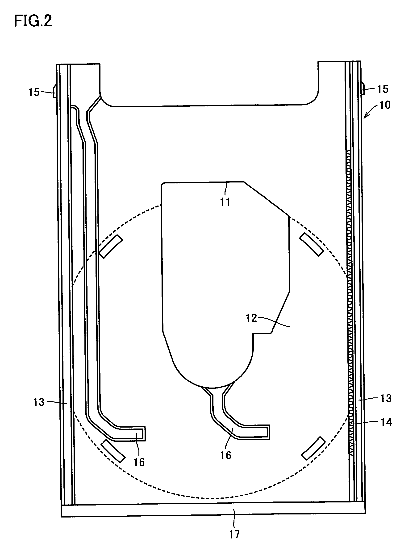
[0017]In this manner, the structure is such that the guide protrusion positioned at the forefront is in surface-contact with the wall surface implementing the guide groove. Accordingly, even if the force in the transversal direction is applied to the disc tray, the force applied to the guide protrusion from the guide groove of the disc tray is distributed, whereby breakage of the guide protrusion will be unlikely. In addition, the guide protrusion positioned at the forefront has a larger width in its root portion, thereby achieving a reinforcement effect of the guide protrusion. Therefore, breakage of the guide protrusion will be further unlikely. Moreover, the root portion of the guide protrusion positioned at the forefront has a width increasing solely on the center side of the disc drive apparatus. In this manner, in an engagement portion of the guide protrusion to the guide groove, a large contact area for engagement of the guide protrusion to the guide groove is ensured in a portion where the guide protrusion does not have an increased width, whereas the reinforcement effect of the guide protrusion is obtained in a portion where the guide protrusion has an increased width. Accordingly, prevention of falling of the disc tray and prevention of breakage of the guide protrusion are both achieved. As described above, an optical disc drive apparatus which is unlikely to be broken and can avoid falling of the disc tray even if a heavy load is applied to the disc tray can be provided.
[0021]In this manner, the guide protrusion positioned at the forefront has a larger width in its root portion, thereby achieving a reinforcement effect of the guide protrusion. Therefore, breakage of the guide protrusion will be further unlikely.

Problems solved by technology

Therefore, breakage of the guide protrusion will be further unlikely.

Method used


Image

  • Optical disc drive apparatus
  • Optical disc drive apparatus
  • Optical disc drive apparatus

Examples


Embodiment Construction

[0035]In the following, one embodiment of the present invention will be described with reference to the figures.

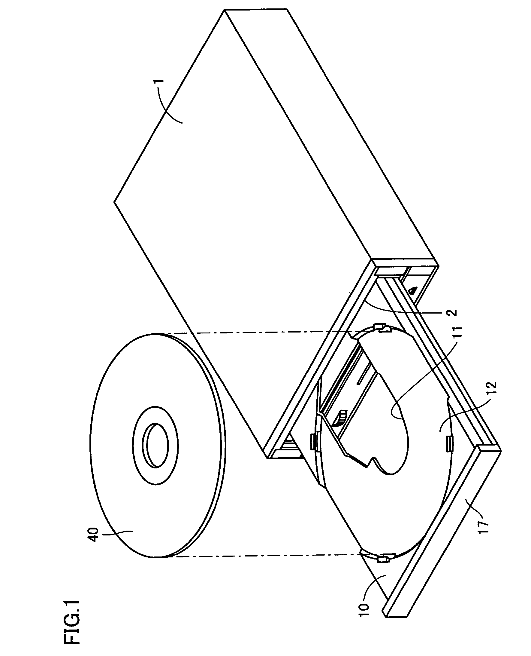
[0036]Referring to FIG. 1, an overall structure of the optical disc drive apparatus in the present embodiment will now be described. As shown in FIG. 1, the optical disc drive apparatus in the present embodiment mainly includes a box-shaped cabinet 1 having an opening 2 on a front face, a frame 20 (see FIG. 3) arranged in cabinet 1, and a disc tray 10 supported by frame 20.

[0037]Loading of an optical disc 40 to the optical disc drive apparatus is performed in the following manner. Optical disc 40 is mounted on a disc mount portion 12 of disc tray 10 drawn out of cabinet 1. Then, disc tray 10 is stored in cabinet 1 using the tray moving mechanism. FIG. 1 shows a state in which disc tray 10 partially comes out in the forward direction from front opening 2 of cabinet 1 and disc tray 10 is positioned at the disc-removable position allowing loading / removing of optical disc 40.

[...


PUM


Abstract

An optical disc drive apparatus includes a frame having a sidewall, and a disc tray supported by the frame. The frame has a supporting portion including a guide rib formed protruding from an inner wall surface of the sidewall and a plurality of guide protrusions formed protruding upward from the guide rib. The disc tray has a supported portion implemented by a guide groove slidably engaging to the plurality of guide protrusions. A guide protrusion positioned at the forefront among the plurality of guide protrusions is structured so as to come in surface-contact with a wall surface implementing the guide groove. With such a structure, an optical disc drive apparatus unlikely to be broken even if a force in a transversal direction is applied to the disc tray while the disc tray is at a disc-removable position can be obtained.

Description

BACKGROUND OF THE INVENTION[0001]1. Field of the Invention[0002]The present invention relates to an optical disc drive apparatus to which a disc recording medium represented by a CD (Compact Disc), a DVD (Digital Versatile Disc), or the like is loaded for reproduction or recording of information.[0003]2. Description of the Background Art[0004]In the optical disc drive apparatus, information is recorded and erased by condensing a light beam emitted from an optical pick-up into a small spot on information recording tracks on a rapidly-rotating disc recording medium (hereinafter, simply referred to as an “optical disc”) and scanning the tracks. When the information recorded on the optical disc is reproduced, the information recording tracks on the rapidly-rotating optical disc are irradiated with a light beam, and the reflected light is received for reading the information.[0005]Generally, the optical disc is loaded to the optical disc drive apparatus of the above-described type by mou...

Claims


Application Information

Patent Timeline
IPC IPC(8): G11B17/04G11B7/00
CPCG11B17/056
Inventor NASU, KAZUMASA
Owner FUNAI ELECTRIC CO LTD
Learn More