Heat distributing hybrid reflector lamp or illumination system

a hybrid reflector and reflector technology, applied in the field of reflector lamps, can solve the problems of increasing the depth of the reflector, increasing the cost, weight and awkwardness of use, and complicating the positioning of the light source in the reflector system, so as to improve the optical efficiency, reduce the concentration of heat, and improve the effect of optical efficiency

Inactive Publication Date: 2006-11-07
WIMBERLY RANDAL LEE
View PDF13 Cites 20 Cited by
  • Summary
  • Abstract
  • Description
  • Claims
  • Application Information

AI Technical Summary

Benefits of technology

[0010]Objects of the invention are to provide a reflector, or reflector lamp, having an improved optical efficiency and a projected beam pattern or gate projection area with substantially more even projection of energy in the desired beam pattern or gate without areas of compressed energy known as hot spots while also lowering the concentration of heat at the center of the projected beam. This permits a lamp design or illumination system having lower power consumption in a more compact form and a system that can be higher in power but not as harmful to lens made of plastic, or the media that it is projecting, or objects that are in the projected beam path.
[0011]These and other objects of the present invention are achieved by providing a lamp unit or a reflector system comprising a reflector and a finite light source wherein the reflector has a parabolic front section or ellipsoidal front section, and a spherical rear section. The front and rear reflector sections are joined together near the intersection of a plane passing through one of the foci of an ellipsoidal front reflector section or the focal point of a parabolic front reflector section and just behind the focal point of the spherical rear reflector section. The focal point of the front reflector section is the exact center point of the finite light source. The focal point of the rear spherical reflector section is just forward of the focal point of the front reflector section. The exact distance forward of this focal point from the forward reflector section focal point is determined by the overall size of the total reflector system and not so far forward that any of the re-reflected light would fall outside of the forward reflector section projected beam. This geometry assures that none of the light produced by the finite light source is trapped inside the spherical rear section and there are no exact reflected energy paths repeated that could create new hot spots or concentrations of heat because of the rearwardly projected light being mirrored back through the exact center of the finite light source and focal point of the front reflector section. Additionally, the spherical rear section with its' slightly forward focal point allows all of the light rays which are reflected by the spherical rear section from a finite light source positioned at the focal point of the front reflector section to be redistributed over the larger surface of the front parabolic or ellipsoidal front section and thus recovering light that would normally be wasted while also un-compressing and re-reflecting that light into the beam pattern in substantially the same geometric configuration as said parabolic or ellipsoidal front sections but distributed more evenly from center to outer edge of said projected beam producing a smoother field.
[0012]Alternately, the amount of heat produced by the reflector lamp or reflector illumination system can be reduced even more if the reflector sections are made of, or coated with, a cold mirror material that allows the heat to pass through and reflects only the visible part of the light being generated by the finite light source. Additionally, the heat radiated from the front of the finite light source can be reduced by placing a hot mirror or hot mirror coated lens in the front of the opening of the reflector lamp or reflector illumination system to reflect the heat and allow the visible light to pass through. Additionally, the quality of the projected beam of light can be enhanced by making the reflective surface of the reflector sections to have facets or fluted areas.

Problems solved by technology

However, if light shining in all directions from a light source is not useful, a reflective surface can be employed to reflect light towards a direction in which the light is useful.
The more widely divergent light rays of the cone of rays, that is, the rays passing relatively nearer to the rim of the reflector, have such a large sideways component of direction so as to fall outside of the desired light pattern or gate and therefore are wasted.
However, there are practical limitations on increasing the depth of the reflector, such as cost, weight and awkwardness of use.
Also, with a given maximum diameter as the reflector is made deeper, the focal point moves closer to the rear surface, which complicates positioning of the light source in reflector systems and if the light source is a filament inside a reflector lamp there is accelerated blackening of the nearby rear area of the reflector due to evaporation of the filament material (usually tungsten).
This accelerated blackening in the reflector lamp can be alleviated by providing a concave recess at the rear portion of the reflector but has the drawback of reducing optical efficiency.
In a reflector or reflector system, as the focal point moves closer to the rear surface, the percentage of reflected energy from the finite light source is compressed and packed much more tightly toward the center of the reflector and, as a result, the opening for the finite light source will remove an area of the reflector that would normally reflect a larger percentage of the light being generated than if it were a shallow reflector, thus reducing optical efficiency of the deep reflector system.
This causes uneven projected beam patterns with concentrated areas know as hot spots in a parabolic reflector system or hot spots and uneven coverage of light causing shadows in the gate of an ellipsoidal reflector system.
These compressed areas also concentrate heat at the center of the projected beam that can be very detrimental to parts of the illumination system and accessories used with these systems such as, but not limited to, color gel material, gobos, plastic lens, projection slides, and film used in motion picture projectors.

Method used


Image

  • Heat distributing hybrid reflector lamp or illumination system
  • Heat distributing hybrid reflector lamp or illumination system
  • Heat distributing hybrid reflector lamp or illumination system

Examples


Embodiment Construction

[0023]Reference will now be made in detail to the present preferred embodiment of the invention, examples of which are illustrated by the accompanying drawings. While the invention will be described in connection with a preferred embodiment, it will be understood that it is not intended to limit the invention to that embodiment.

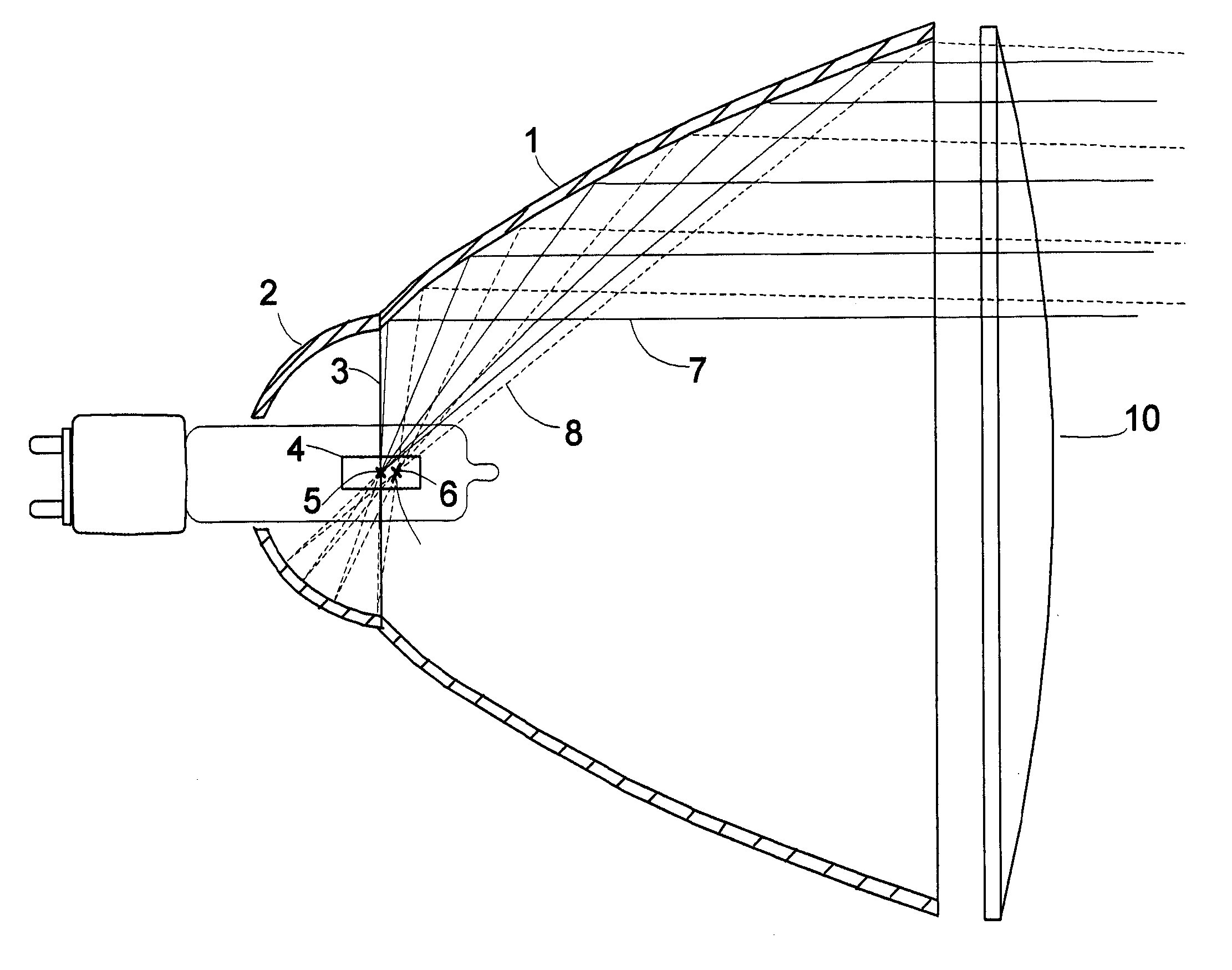
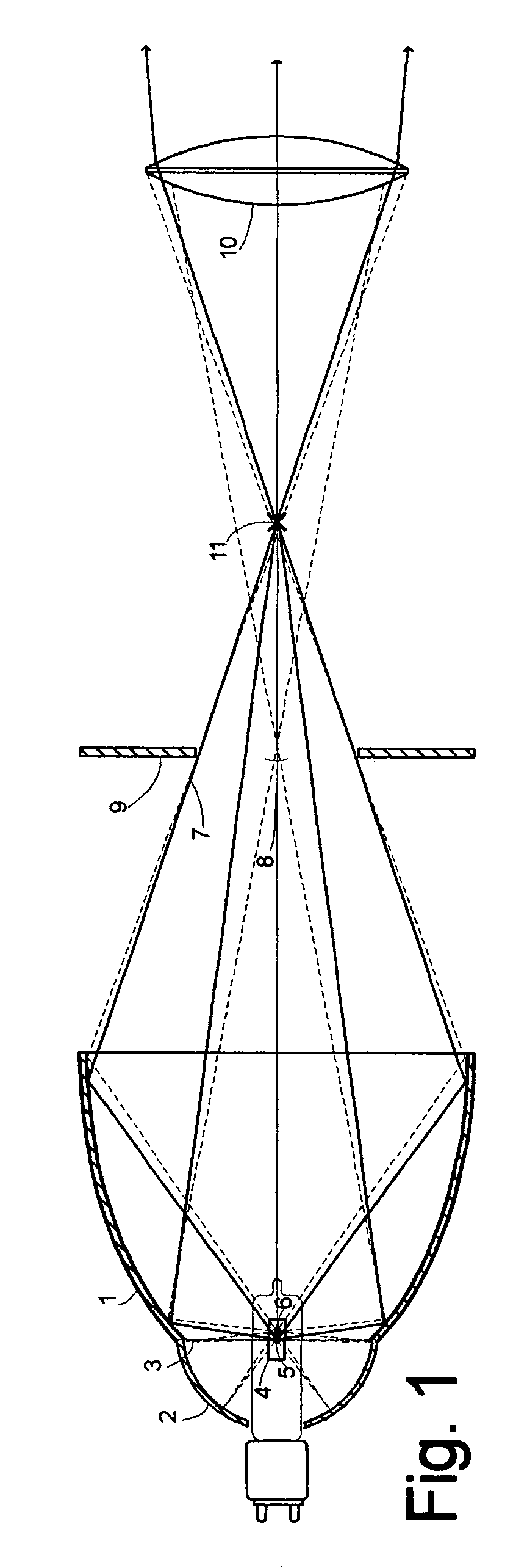
[0024]FIG. 1 is a schematic diagram of a first embodiment of an incandescent illumination system in accordance with the invention. The reflector has an ellipsoidal front section 1 and a spherical rear section 2. The front and rear reflector sections are joined together near the intersection of a plane 3 passing through one of the foci 5 of the ellipsoidal front reflector section and just behind the focal point of the spherical rear reflector section 6. The focal point of the front reflector section is the approximate center point of the finite light source 4. The focal point of the rear spherical reflector section 6 is just forward of the focal point of the f...


PUM


Abstract

A reflector lamp or illumination system comprising a concave reflector having a parabolic or ellipsoidal front section and a spherical rear section with it's focal point just ahead of the focal point of the front section, and a finite light source located at the focal point of the front section. The reflector sections are dimensioned so that light rays from the finite light source which are reflected by the spherical rear section become re-reflected by the front section and distributed more evenly in said projected beam pattern with the energy rays filling back in from the edge to the center. Additionally the light rays, re-reflected by the front section, are made up of uncompressed light and energy components which provide a beam pattern which is substantially more even in light and energy distribution, does not have compressed light and energy producing hot spots of light and heat at the center of the projected beam pattern or gate, and is therefore less harmful to parts such as lighting fixture parts, plastic lens and items being projected such as plastic color media, film, and slides.

Description

[0001]This application claims the benefit of U.S. Provisional Application No. 60 / 497,212, filed Aug. 21, 2003.REFERENCES CITED[0002]U.S. Pat. No. 6,488,379 B2Dec. 3, 2002KaneU.S. Pat. No. 6,168,293 B1Jan. 2, 2001Lieszkovszky et. alU.S. Pat. No. 4,755,918Jul. 5, 1988Pristash et. alU.S. Pat. No. 4,654,758Mar. 31, 1987Szekacs et. alU.S. Pat. No. 4,447,865May 8, 1984VanHorn et. alU.S. Pat. No. 3,443,086May 6, 1969RikisU.S. Pat. No. 3,267,274Nov. 26, 1963JohnsonU.S. Pat. No. 1,995,012Mar. 19, 1935RivierU.S. Pat. No. 1,575,327Mar. 2, 1926Garford et. alTECHNICAL FIELD[0003]The present invention is in the field of reflector lamps and more particularly in the field of optical reflectors for use in collecting a high proportion of the emitted light and projecting a high-intensity beam.BACKGROUND OF THE INVENTION[0004]Light reflectors have long been used to bounce light off of a reflective surface. Light generally shines in all directions from a light source. However, if light shining in all di...

Claims


Application Information

Patent Timeline
Patent Type & Authority Patents(United States)
IPC IPC(8): F21V7/06F21V11/00F21V7/08F21V7/09F21V13/04
CPCF21V7/09F21V13/04
Inventor WIMBERLY, RANDAL LEE
Owner WIMBERLY RANDAL LEE
Why Eureka
Try Eureka