Electrical wiring device with arc minimizer switch assembly and method

a technology of arc minimizer switch and electrical wiring device, which is applied in the direction of contact mechanism, electrical apparatus, contact, etc., can solve the problems of heating to ignite nearby combustibles, shock hazards, fire hazards,

Inactive Publication Date: 2006-11-07
PASS SEYMOUR
View PDF24 Cites 9 Cited by
  • Summary
  • Abstract
  • Description
  • Claims
  • Application Information

AI Technical Summary

Benefits of technology

[0010]Embodiments of the invention are directed to an electrical wiring device including a switch assembly and to an ele

Problems solved by technology

Ground fault conditions are an unintended current path from the line conductor having faulty or damaged insulation to ground.
The shock hazard occurs when someone contacts ground and the line conductor at the same time.
A fire hazard may occur if the ground fault current results in sufficient heating to ignite nearby combustibles.
Hazardous arc fault conditions (known as series arc faults) may result from a poor electrical connection in the electrical distribution system supplying power to the load.
Hazardous arcing conditions (known as parallel arc faults) may occur between a line to line conductor, line to neutral conductor, or line to ground conductor, due to faulty or damaged insulation.
One disadvantage of known combination devices, herein illustrated as a switch in combination with a protection component, is that the user accessible switch toggles in a motion that is parallel to the minor (latitudinal) axis of the device.
The user of the device does not find such rocking motion to be ergonomic.
Another disadvantage is that such rocking motion is not consistent with other wiring devices whose rocking motion is perpendicular to the minor axis of the device.
Another disadvantage of known combination devices is that the user accessible switch portion of the combination device has been limited in number to a single switch.
A

Method used


Image

  • Electrical wiring device with arc minimizer switch assembly and method
  • Electrical wiring device with arc minimizer switch assembly and method
  • Electrical wiring device with arc minimizer switch assembly and method

Examples


Embodiment Construction

[0020]A particular embodiment of the invention is directed to an electrical wiring device configured to be disposed in an electrical distribution system including a power source for providing power to a load. The device includes a compact switch assembly. Although the components, design and principles of operation of the switch apply to a single switch, it will be understood that the description is equally applicable to two or more switches adjacently disposed in a housing.

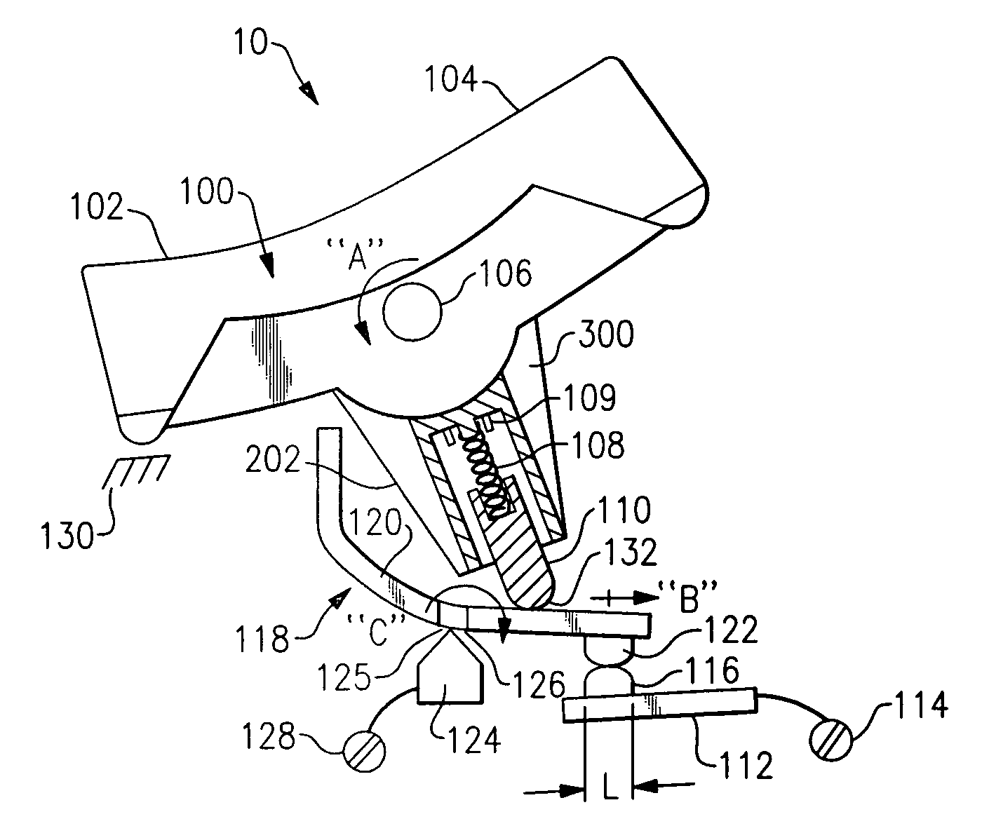
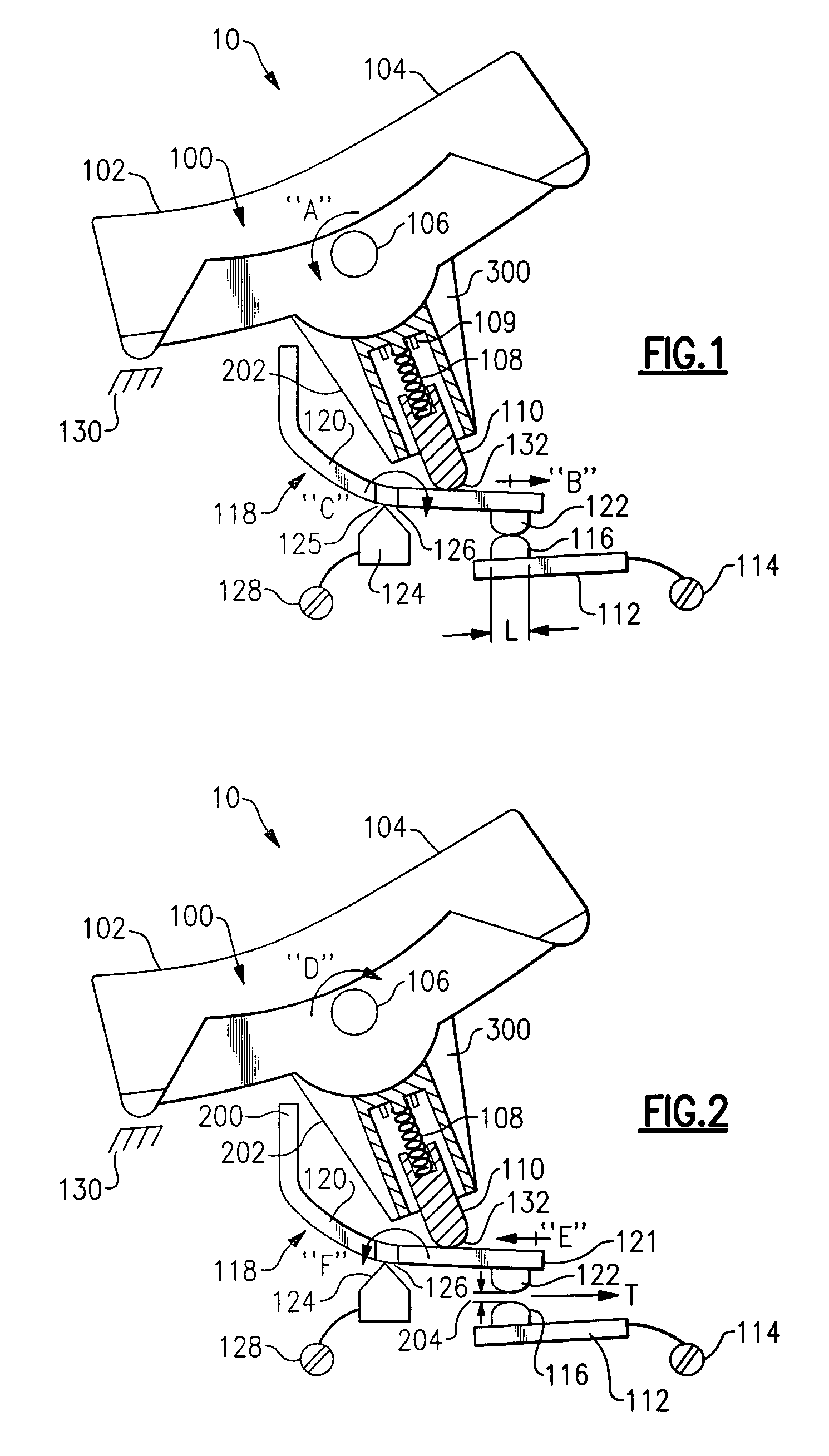
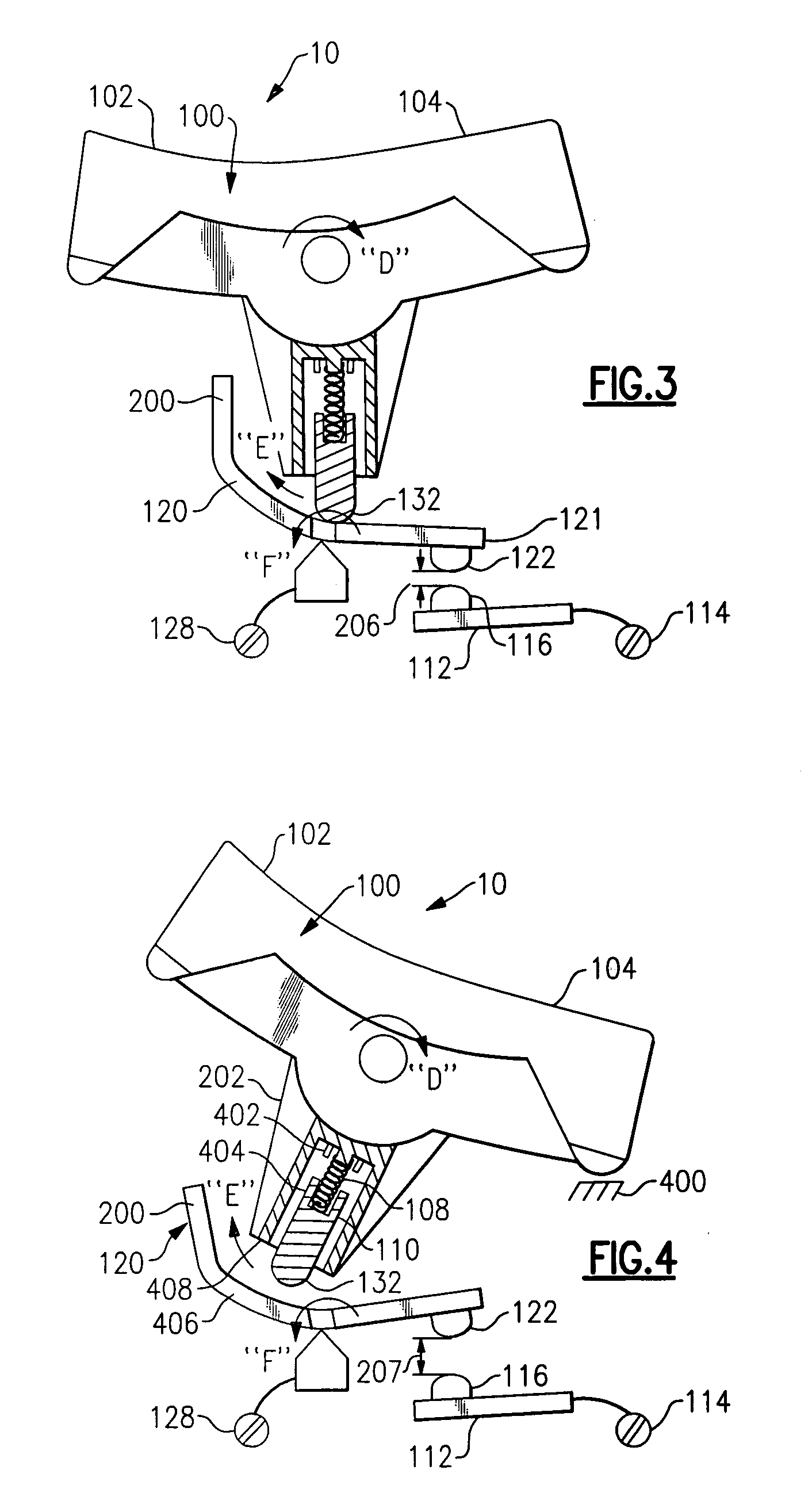
[0021]FIGS. 1 through 4 illustrate the operative features of a compact switch assembly 10 according to an embodiment of the invention. The switch assembly is incorporated in an electrical wiring device, as illustrated by example as device 500 in FIG. 5, intended to be disposed in an electrical distribution system (not shown).

[0022]Referring to FIGS. 1 and 2, the switch assembly 10 is shown in the closed contact position. The switch assembly includes a rocker assembly 100 having a user accessible surface 104 for ac...


PUM


Abstract

An electrical wiring device configured to be disposed in an electrical distribution system including a power source for providing power to a load, including a compact switch assembly. The compact switch assembly includes a rocker assembly, a fixed contact assembly and a moveable contact assembly. By design and interaction between surfaces of the rocker assembly and the moveable contact assembly, permanent switch contact closure due to contact arc welding is avoided. A pivot member including a (moveable) contact is opened to a first contact separation distance within a given time and then to a second contact separation distance via user supplied force to a user accessible surface. A combination device is also disclosed including a circuit interrupter configured to provide power to a portion of the electrical distribution system in the closed contact position and to interrupt power from a portion of the electrical distribution system in the open contact position in response to a predetermined fault condition in the electrical distribution system. A method for opening a set of closed switch contacts in a switch assembly of an electrical device configured to provide the rated current of an AC electrical distribution system to a load is further disclosed.

Description

RELATED APPLICATION DATA[0001]This application is a continuation-in-part of U.S. Ser. No. 10 / 994,662 filed on Nov. 22, 2004, which itself claims priority to U.S. Provisional Application Ser. No. 60 / 553,795 filed on Mar. 16, 2004, and claims the benefit of priority to these prior applications under 35 U.S.C. §119 and §120. These applications are both herein incorporated by reference in their entireties.FIELD OF THE INVENTION[0002]Embodiments of the invention generally relate to the field of electrical wiring devices and, more particularly, to an electrical wiring device including a switch assembly designed to eliminate contact arcing and welding, and to a method for opening a set of closed switch contacts.BACKGROUND OF THE INVENTION[0003]The switch component of an electrical wiring device typically includes a user accessible switch arm, rocker paddle, push button, touch pad, etc. (“switching surface”), a lever arm or suitable linkage attached to the backside of the switching surface,...

Claims


Application Information

Patent Timeline
IPC IPC(8): H01H21/00
CPCH01H23/168H01H1/50H01H3/001H01H23/166H01H23/205
Inventor RADOSAVLJEVIC, DEJANWEEKS, RICHARD
Owner PASS SEYMOUR
Why Eureka
Try Eureka