

Moving belt sensor
a moving belt and sensor technology, applied in the direction of magnetic variables, instruments, and using reradiation, can solve the problems of imposing speed limitations on the conveying assembly, and achieve the effects of improving the system efficiency, ensuring the accuracy of detection, and ensuring the precise position of hidden objects
- Summary
- Abstract
- Description
- Claims
- Application Information
AI Technical Summary
Benefits of technology
Problems solved by technology
Method used
Image

Examples
Embodiment Construction
[0002]This invention was made with Government support under contract no. DAAB15-00-C-1008, task no. SMBA1 awarded by the Army. The Government has certain rights in this invention.
BACKGROUND OF THE INVENTION
[0003]1. Field of the Invention
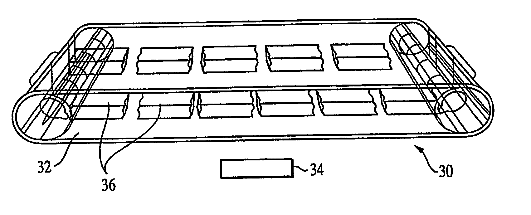
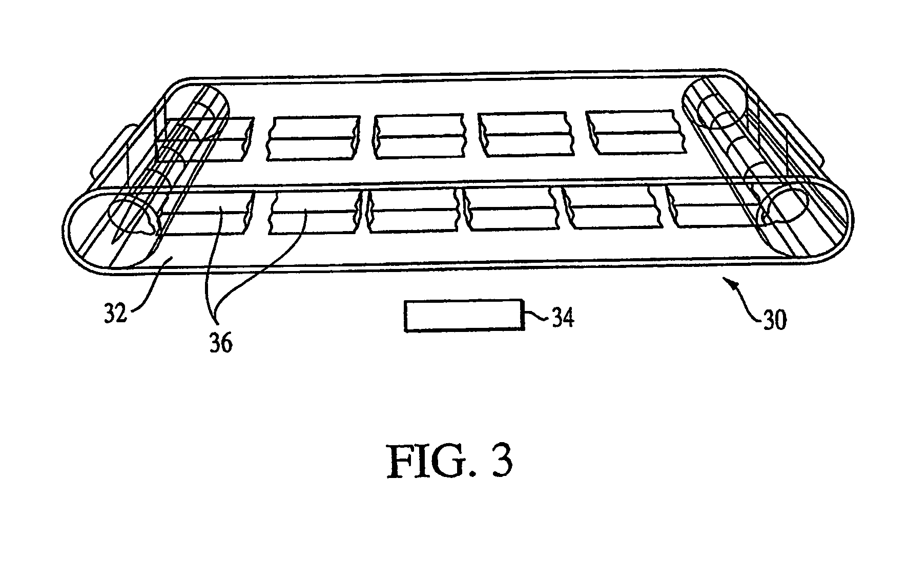
[0004]The present invention generally relates to an object detection system coupled to and displaceable with a closed-loop belt.
[0005]2. Description of the Related Art
[0006]Landmines, airport luggage conveyor belts and food processing plant conveyor belts all have a need for detection of metal objects in a fast and efficient manner. In addition to detection of metal, these metal detectors sometimes must classify or discriminate the type of metal from clutter objects. This is particularly important for landmine detection to reject the potentially high incidence of metal clutter in the environment.
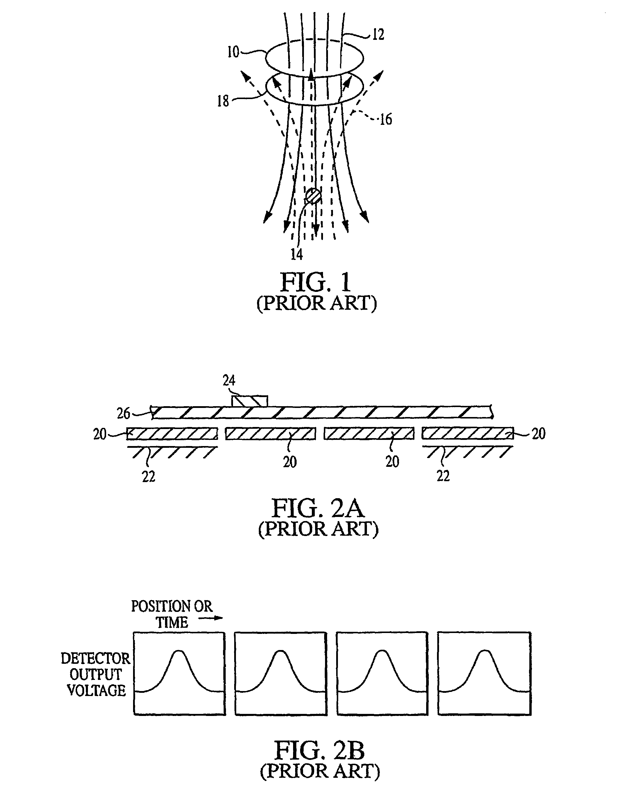
[0007]As shown in FIG. 1, the operation of metal detectors is based upon the principles of electromagnetic induction. Usually, a metal detector includes one ...
PUM
 Abstract
Description
Claims
Application Information