Multiple bands type antenna and method for producing the same

a multi-band type, antenna technology, applied in the direction of resonant antennas, non-resonant long antennas, collapsable antennas, etc., can solve the problems of reducing the efficiency of the antenna, unbalance condition, and difficulty in impedance matching, so as to improve the antenna efficiency

Inactive Publication Date: 2006-11-07
E M W ANTENNA CO LTD
View PDF10 Cites 8 Cited by
  • Summary
  • Abstract
  • Description
  • Claims
  • Application Information

AI Technical Summary

Benefits of technology

[0018]Accordingly, the present invention has been made keeping in mind the above problems occurring in the prior art, and an object of the present invention is to provide a multiple band-type antenna and method of producing the same, which can improve the efficiency of the antenna by overcoming an unbalance condition that is a problem in the conventional antenna, and can immediately cope with frequency variation resulting from various services because the antenna can accommodate various frequencies.

Problems solved by technology

These methods cause an unbalance condition between feeding lines of an antenna, so impedance matching becomes quite difficult.
Additionally, a contact point between the antenna and the feeding line frequently varies, so the characteristics of the antenna are not constant, thus reducing the efficiency of the antenna.
The conventional antenna is problematic in that it cannot overcome the unbalance condition that is a problem in the conventional antenna, thus causing low efficiency, and it is difficult to miniaturize.
This is the inherent unbalance condition of the conventional helical antenna that is used as a general wireless communications receiving antenna.
Additionally, the conventional antenna is problematic in that the efficiency of the conventional antenna is deteriorated because the unbalance condition that is a problem in the conventional antenna is not overcome.

Method used


Image

  • Multiple bands type antenna and method for producing the same
  • Multiple bands type antenna and method for producing the same
  • Multiple bands type antenna and method for producing the same

Examples


Embodiment Construction

[0035]An embodiment of the present invention will be described in detail with reference to the attached drawings below.

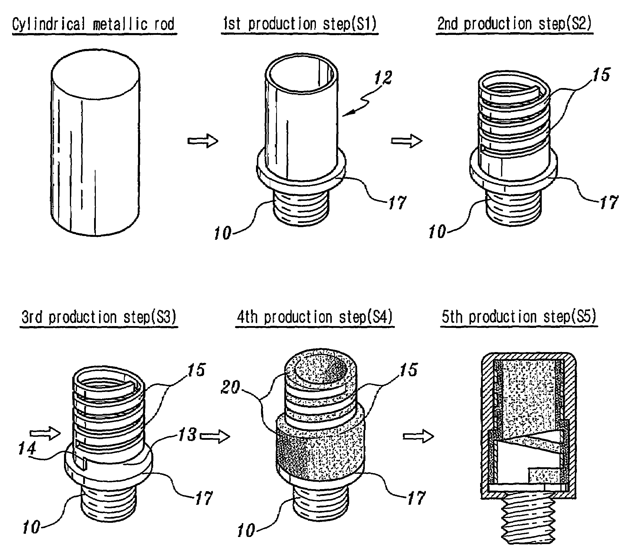
[0036]FIG. 5a is a view showing a method of producing a multiple band-type antenna to which the technology of the present invention is applied. Referring to this drawing, a connector 10 is formed by externally threading the circumferential surface of a cylindrical metallic rod having a certain length and a certain diameter and a workpiece is processed to have a hollow processed portion 12 above the connector 10 through the 1st production step S1. A connection member 14 having a space 13 is formed at a position where the hollow processed portion 12 formed through the 1st production step S1 and the connector 10 are positioned near each other through the 2nd production step S2.

[0037]Meanwhile, a first helical antenna element 15 is formed to have a helical shape from a position spaced apart from the space 13 of the connection member 14 through the 3rd production step S3...


PUM


Abstract

The present invention relates to a multiple band-type antenna and method of producing the same. In the present invention, a connector member formed by cutting a cylindrical metallic rod and a first helical antenna are integral through a connection member. A space forming an impedance transformer is formed at the connection member for thereby widening a band region based on a series inductance effect. A helical antenna and a whip antenna are additionally installed at a center of the dielectric surrounding the inner and outer sides of the first helical antenna and the connection member for thereby enhancing an efficiency of the antenna by overcoming the unbalance problems encountered in the conventional art.

Description

TECHNICAL FIELD OF THE INVENTION[0001]This application is a 371 of PCT / KR02 / 01212 Jun. 25, 2002.[0002]The present invention relates to a multiple bands type antenna and a method for producing the same, and in particular to a multiple bands type antenna and a method for producing the same in which a connector and a helical antenna get integral using a connection member by cutting a cylindrical metal rod, and an impedance transformer is formed in such a manner that a certain space is formed in the connection member.BACKGROUND OF THE INVENTION[0003]In a general feeding structure of a conventional small-sized antenna used in wireless communications, a coaxial line is directly brought into contact with an antenna to perform feeding. For monopole antennas, a + part of a coaxial line is brought into contact with an antenna to perform feeding. For dipole antennas, + and − parts of a coaxial line are brought into contact with an antenna to perform feeding.[0004]These methods cause an unbalan...

Claims


Application Information

Patent Timeline
Patent Type & Authority Patents(United States)
IPC IPC(8): H01Q1/36H01Q1/24H01Q1/10H01Q1/50H01Q5/00H01Q9/16H01Q9/30H01Q11/08H01Q21/30
CPCH01Q1/242H01Q1/362H01Q1/50H01Q5/40H01Q11/08H01Q21/30H01Q5/378H01Q9/16
Inventor RYOU, BYUNG-HOONSUNG, WEON-MO
Owner E M W ANTENNA CO LTD
Why Eureka
Try Eureka