Digital television receiver with remote tuner for driving transmission line with intermediate-frequency signal

a technology of transmission line and tuner, which is applied in the direction of transmission, selective content distribution, television systems, etc., can solve the problems of simultaneous complete loss of picture and sound, loss, and rare loss of viewable pictur

Inactive Publication Date: 2006-11-07
LIMBERG ALLEN LE ROY
View PDF9 Cites 26 Cited by
  • Summary
  • Abstract
  • Description
  • Claims
  • Application Information

AI Technical Summary

Benefits of technology

[0013]An outdoor-antenna digital television receiver system constructed in accordance with the invention has an electrically controlled remote tuner located close to the antenna. In response to a remote control signal, the remote tuner selects a particular radio-frequency digital television signal to be received, converts that RF DTV signal to an intermediate-frequency digital television signal of prescribed carrier frequency, and drives a downlead transmission line, preferably a coaxial cable. Indoors, the downlead transmission line is provided with an echo-free termination for the frequency range in which the IF DTV signal reposes. This echo-free termination may be in a “set-top” box which includes a frequency uponverter that converts the IF DTV signal back to an RF DTV signal for reception by a conventional digital television receiver. Alternatively, the echo-free termination may be in a special DTV receiver without a local tuner. In such a special DTV receiver the IF DTV signal developed across the echo-free termination is supplied to circuitry for demodulation and analog-to-digital conversion, which circuitry supplies digitized baseband DTV signal.

Problems solved by technology

While multipath reception causes ghost images on the television viewscreen during analog TV signal reception, complete loss of viewable picture rarely occurs and that loss is usually due to loss of display synchronization or excessive noisiness of the picture owing to weak-signal reception.
Multipath or other echo-producing conditions can cause simultaneous complete loss of picture and sound during DTV signal reception.
Such loss occurs whenever the error rate of data slicing the baseband DTV signal is too great to be correctable in reliance upon forward-error-correction coding.
This adaptive filtering suppresses the pre-echoes and post-echoes accompanying the principal signal, but exacts a penalty in carrier-to-noise ratio (C / N).
If C / N becomes too small, data slicing of the baseband DTV signal exhibits excessive error because the noise is large enough to cause errors in distinguishing between data modulation levels.
Also, changes in field strength and multipath conditions may occur with indoor antenna reception owing to people and pets moving around in the antenna field.
The outdoor antenna is coupled to the indoor receiver via a download, which downlead exhibits a transmission loss that is often significant.
This overload condition is not only deleterious to the linearity of a strong DTV signal, but causes cross-modulation with any accompanying weaker DTV signal, adversely affecting its linearity as well.
These losses of linearity will raise the rate of errors in data slicing the baseband DTV signal sufficiently that the errors no longer are correctable in reliance upon forward-error-correction coding.
Generally, a TV service technician in the field will be unable to solve these reception problems optimally.
When a wide-band RF amplifier close to the antenna is used for driving a coaxial-cable downlead to an indoor receiver, there is difficulty in terminating this transmission line with its characteristic impedance for all of the TV broadcast channels.
The design of a tuner that exhibits characteristic impedance at its RF input connection for every channel in each of the three discrete frequency ranges is extremely difficult, even when different RF stages are used for the UHF and VHF bands.
These devices are not well suited for inclusion within a remote tuner that is located nearby an outdoor antenna or incorporated into the structure of the antenna.

Method used


Image

  • Digital television receiver with remote tuner for driving transmission line with intermediate-frequency signal
  • Digital television receiver with remote tuner for driving transmission line with intermediate-frequency signal
  • Digital television receiver with remote tuner for driving transmission line with intermediate-frequency signal

Examples


Embodiment Construction

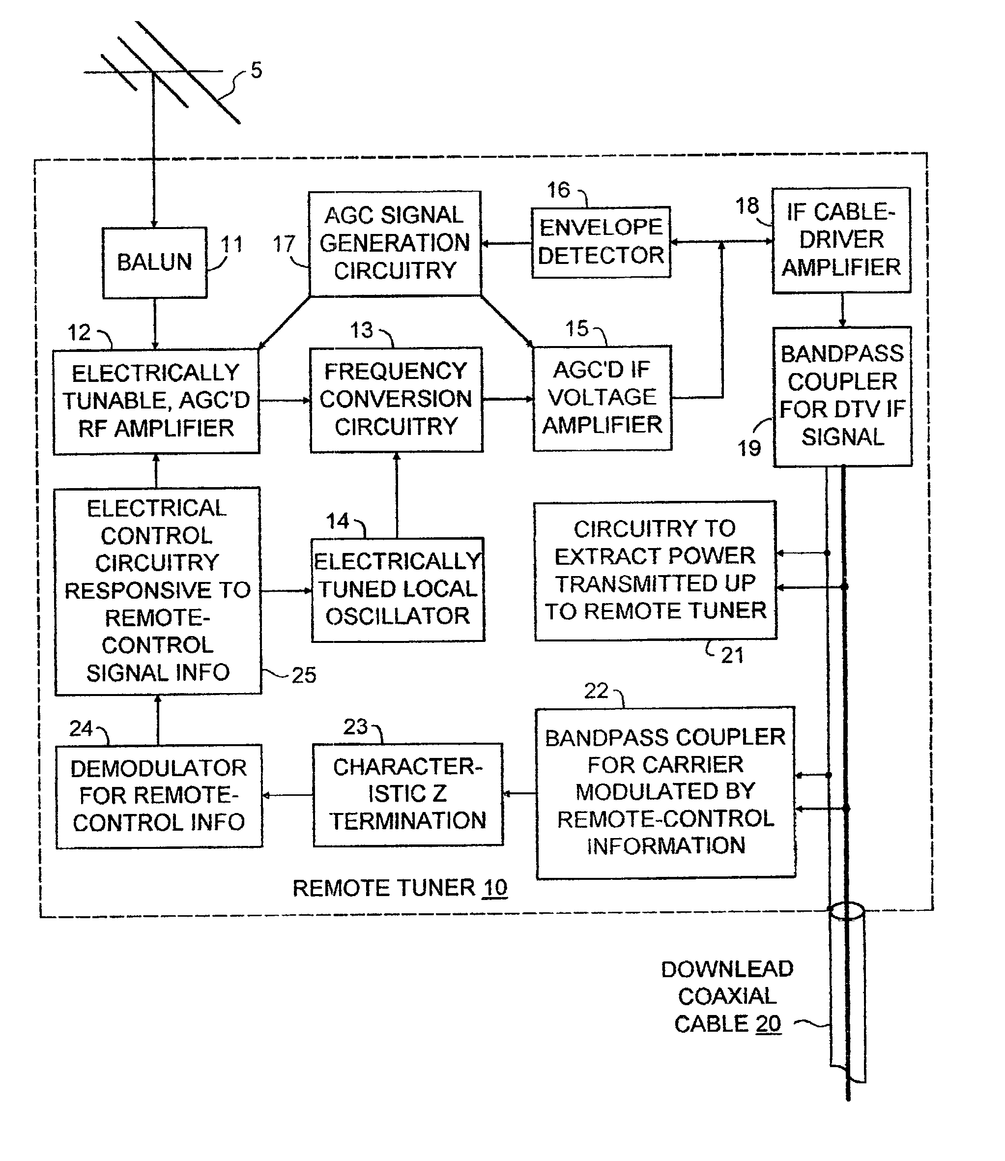
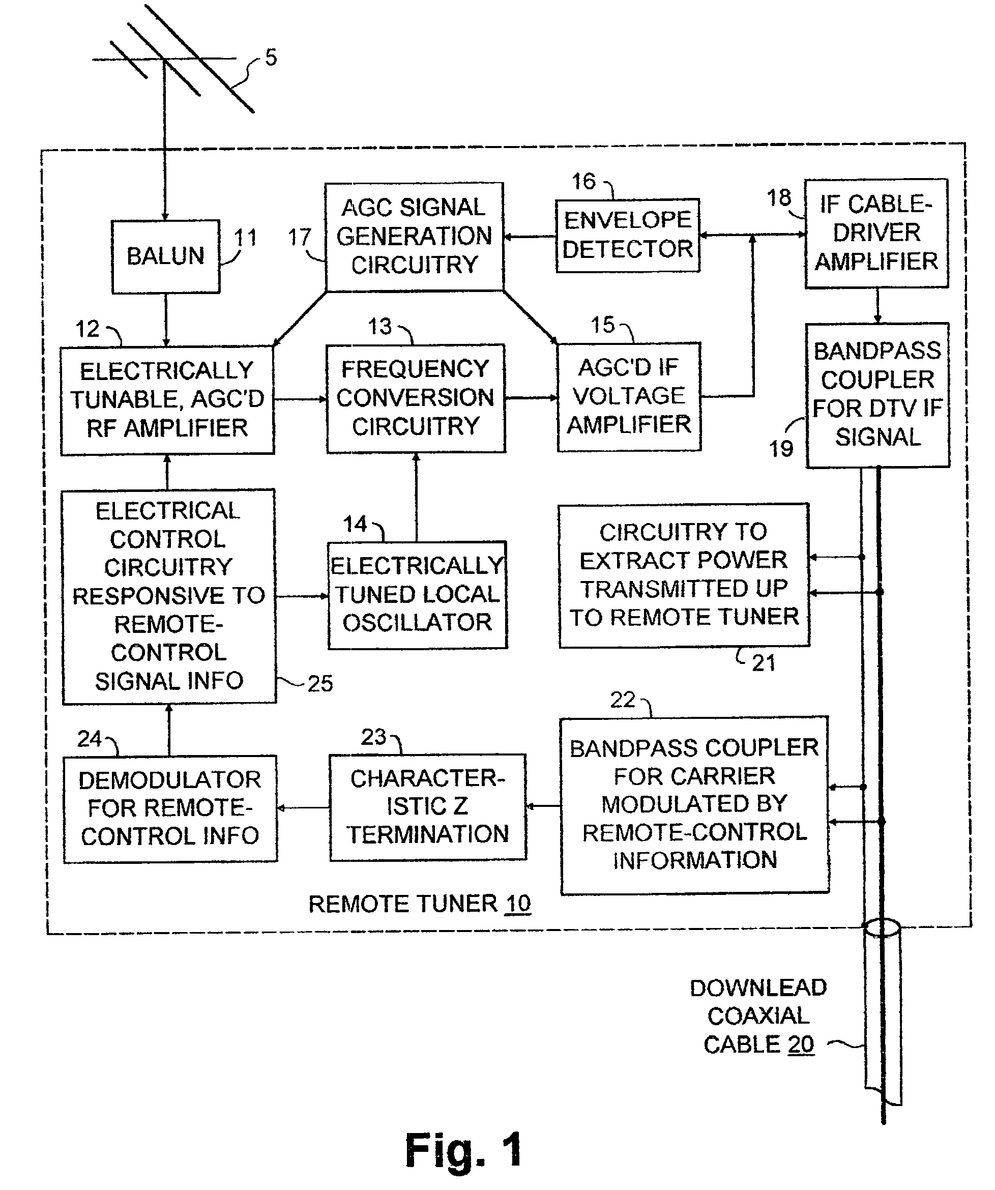
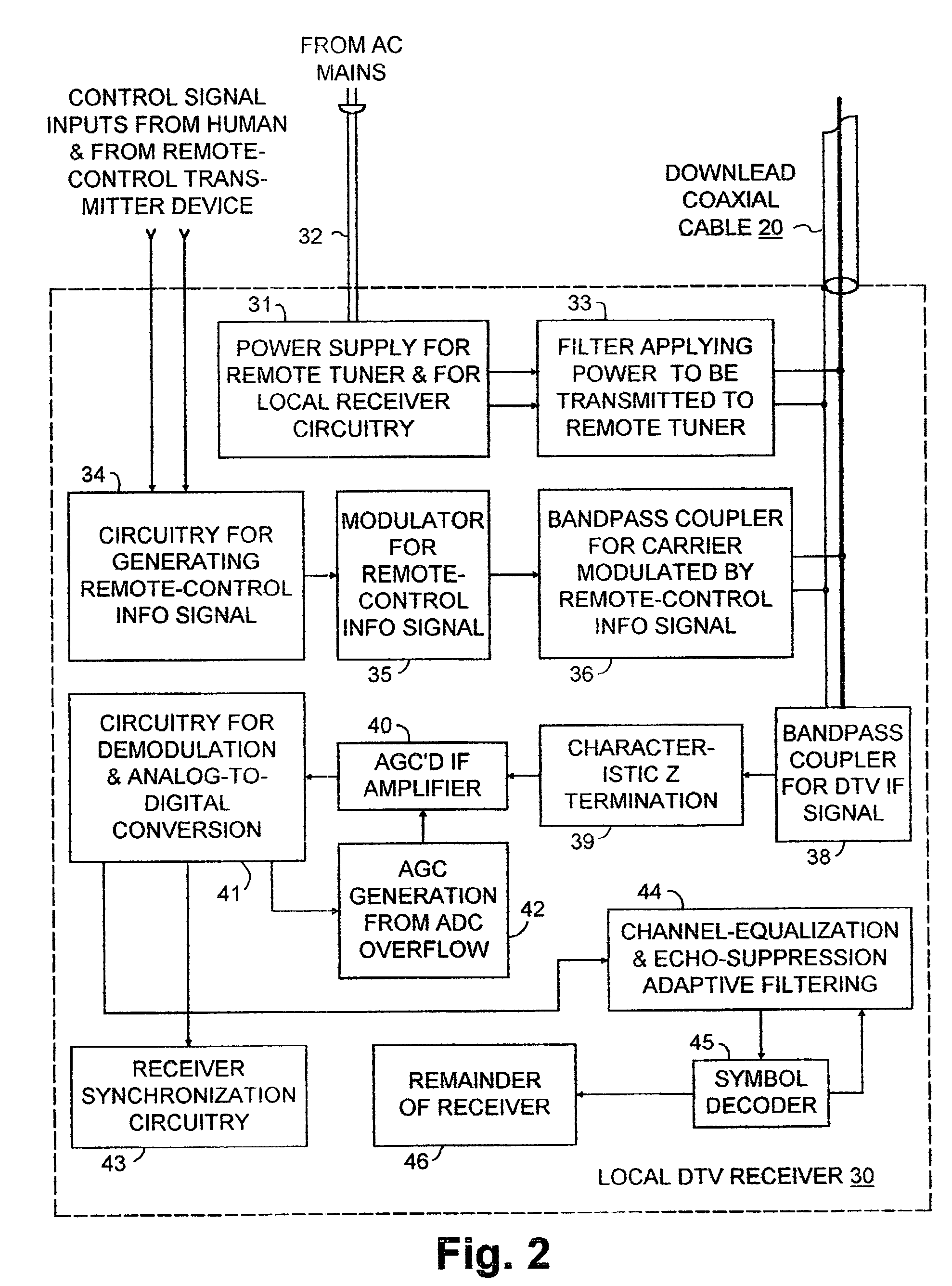
[0021]FIG. 1 shows an outdoor antenna 5 connected to a nearby tuner 10 constructed in accordance with the invention for being located remotely from the rest of the digital television receiver, which is located indoors. The antenna 5 connects via a balun 11 to a radio-frequency amplifier stage 12 in the remote tuner 10 and supplies that RF amplifier stage 12 with radio-frequency signal. The amplified radio-frequency signal from the RF amplifier stage 12 is converted to an intermediate-frequency signal by frequency-conversion circuitry 13 in the tuner 10, which frequency-conversion circuitry 13 includes an electrically tunable local oscillator 14 for selecting the DTV channel to be converted to the intermediate-frequency signal. In actual practice, the electrically tunable local oscillator 14 is likely in fact to comprise one of the types of circuitry commonly referred to as a “frequency synthesizer”, which types of circuitry are already employed in TV receivers.

[0022]The tuner 10 may...


PUM


Abstract

An outdoor-antenna digital television receiver system has an electrically controlled remote tuner located close to the antenna. In response to a remote control signal, the remote tuner selects a particular radio-frequency digital television signal to be received, converts that RF DTV signal to an intermediate-frequency digital television signal of prescribed carrier frequency, and drives a downlead transmission line, preferably a coaxial cable. Indoors, the downlead transmission line is provided with an echo-free termination This echo-free termination may be in a “set-top” box that includes a frequency up-conveter that converts the IF DTV signal back to an RF DTV signal for reception by a conventional digital television receiver. Alternatively, the echo-free termination may be in a special DTV receiver without a local tuner. In such a special DTV receiver the IF DTV signal developed across the echo-free termination is supplied to circuitry for demodulation and analog-to-digital conversion, which circuitry supplies digitized baseband DTV signal.

Description

[0001]The invention relates to receving for digital television (DTV) signals.BACKGROUND OF THE INVENTION[0002]The digital television (DTV) signals currently broadcast in the United States of America employ 8-level vestigial-sideband amplitude-modulation of a suppressed carrier 310 kilohertz above the lower boundary frequency of a 6-megahertz-wide television channel allocation. A fixed-amplitude pilot carrier at the frequency and phase of the suppressed carrier accompanies this 8-VSB signal. The 8-VSB signal is demodulated in the digital television receiver to recover an 8-level baseband DTV signal subjected to data slicing procedures during symbol decoding. Linearity of the DTV signal during its transmission and reception must be preserved, so that the data slicing procedures have low enough rate of errors that the errors are nearly always correctable in reliance upon forward-error-correction coding. The 8-VSB signal has a 10.76 million symbols per second baud rate. Therefore, good ...

Claims


Application Information

Patent Timeline
Patent Type & Authority Patents(United States)
IPC IPC(8): H04N5/44H04N7/10H04N21/40
CPCH04N5/4401H04N5/4446H04N7/106H04N21/40H04N21/414H04N21/426H04N21/4436
Inventor LIMBERG, ALLEN LE ROY
Owner LIMBERG ALLEN LE ROY
Why Eureka
Try Eureka