
Image forming apparatus and image forming method

a technology forming method, which is applied in the field of image forming apparatus, can solve the problems of increasing the rotation number of the rotary polygon, shortening increasing the noise, so as to shorten the useful life of the motor, shorten the printing speed, and increase the noise

Inactive Publication Date: 2006-11-07
KYOCERA DOCUMENT SOLUTIONS INC
View PDF3 Cites 4 Cited by
  • Summary
  • Abstract
  • Description
  • Claims
  • Application Information

AI Technical Summary

Benefits of technology

The present invention provides an image forming apparatus that can change the resolution in the sub-scanning direction without increasing noise, shortening the life of the motor, or requiring a costly motor. The apparatus includes a laser emitter, a reflector, a driver, a resolution designation acceptor, and an emission controller. The resolution designation acceptor can select between a low resolution and a high resolution. The emission controller controls the laser emitter to selectively emit the laser beam along the predetermined scanning line in a forward direction or a backward direction depending on the designated resolution. This arrangement allows for changing the resolution in printing without the drawbacks of increasing noise, shortening motor life, or lowering printing speed.

Problems solved by technology

In the image forming apparatus with the increased rotation number of the rotary polygon mirror, various drawbacks, resulting from the increase of the rotation number of the rotary polygon mirror, may occur such as increase of a noise, shortening of the useful life of a motor, or required use of a costly motor.
Also, a clock for outputting image data is required to be increased, which may lead to unduly increase of radiation.

Method used


Image

  • Image forming apparatus and image forming method
  • Image forming apparatus and image forming method
  • Image forming apparatus and image forming method

Examples


Embodiment Construction

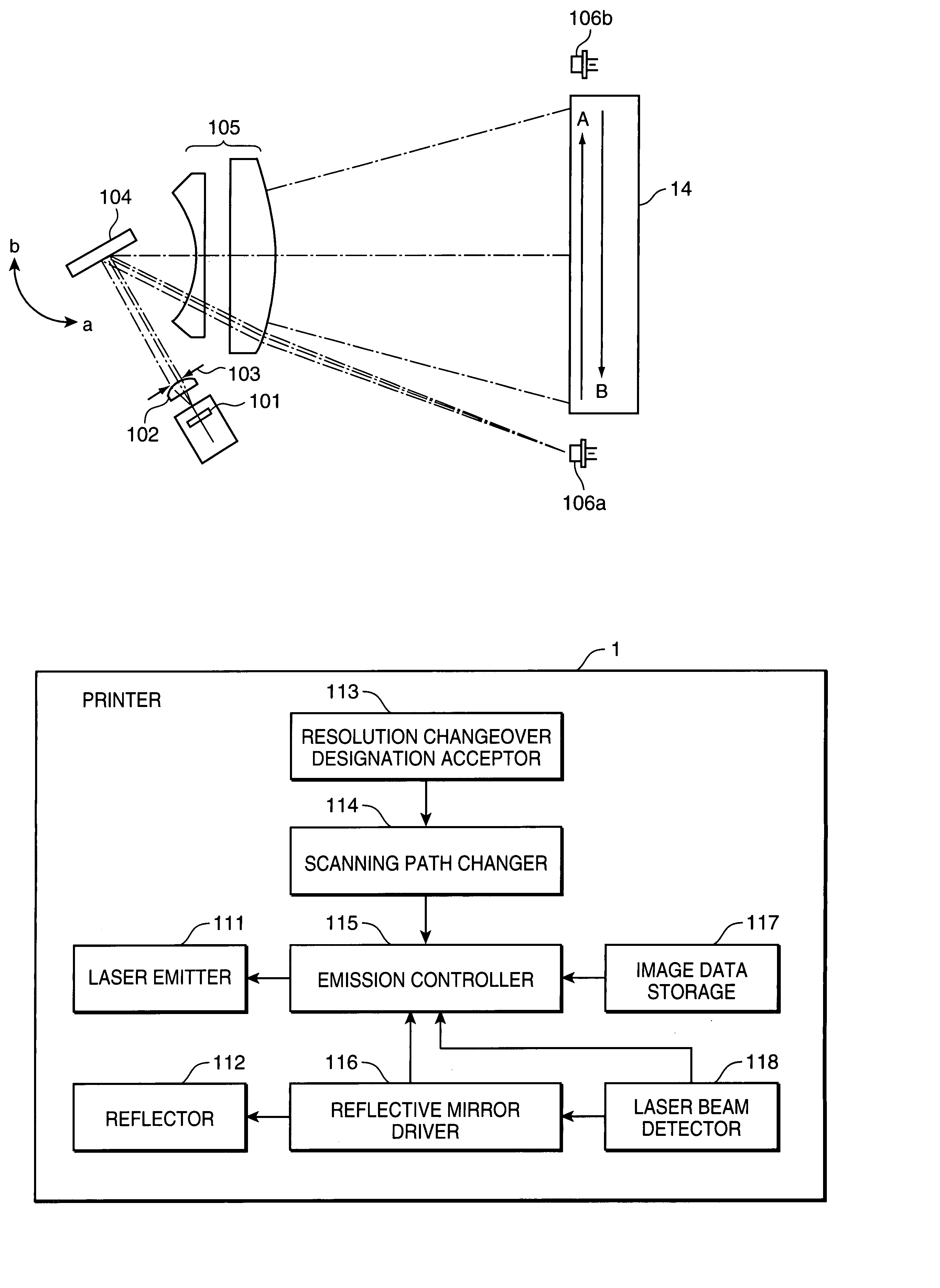
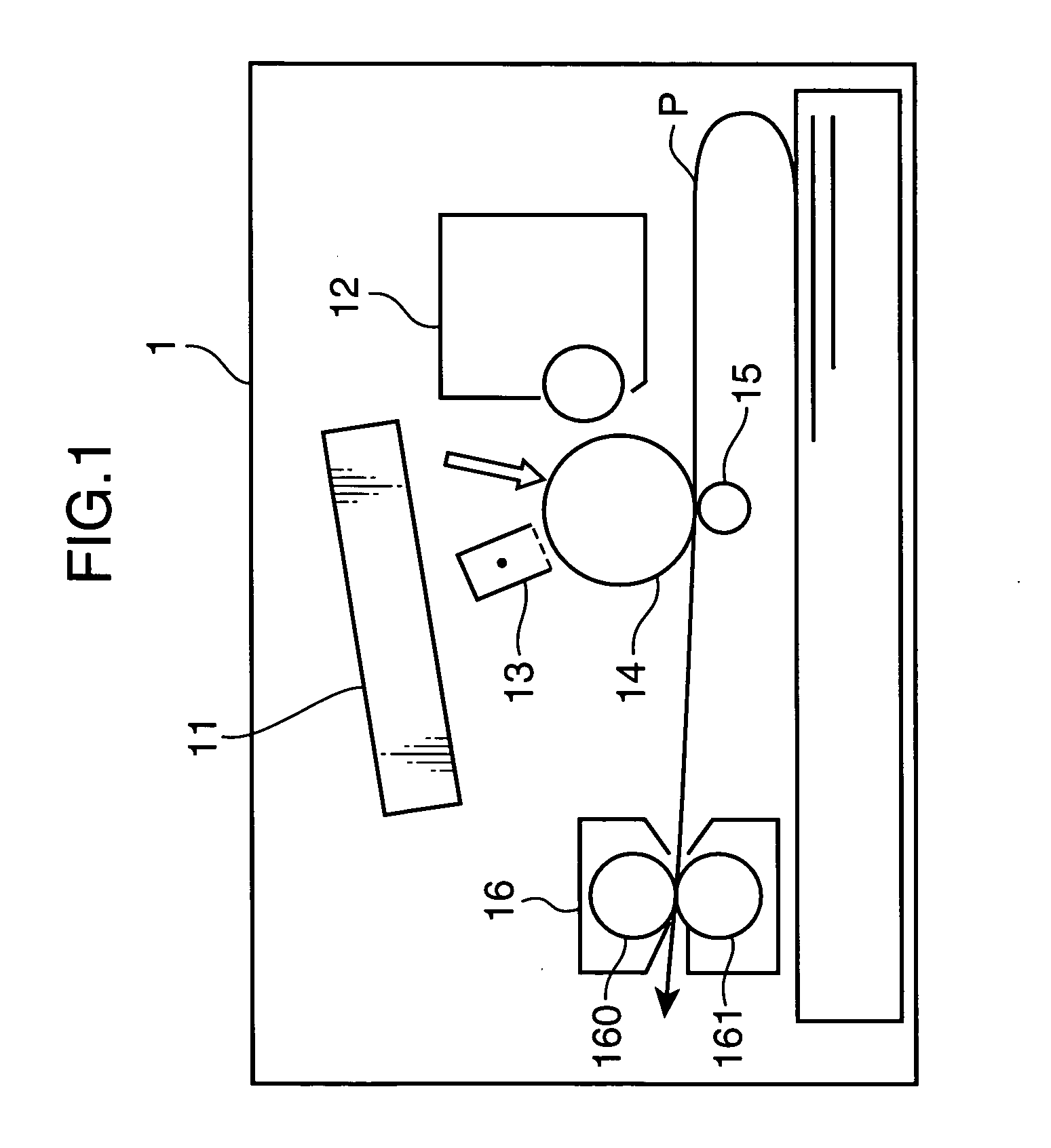
[0016]In the following, an embodiment of the invention is described referring to the drawings. FIG. 1 is an illustration showing a mechanical construction of a printer 1 as an example of an image forming apparatus in accordance with an embodiment of the invention. The printer 1 includes, as mechanical components, a laser scanner 11, a developer 12, a charger 13, a photosensitive drum 14, a transfer roller 15, and a fixing unit 16.

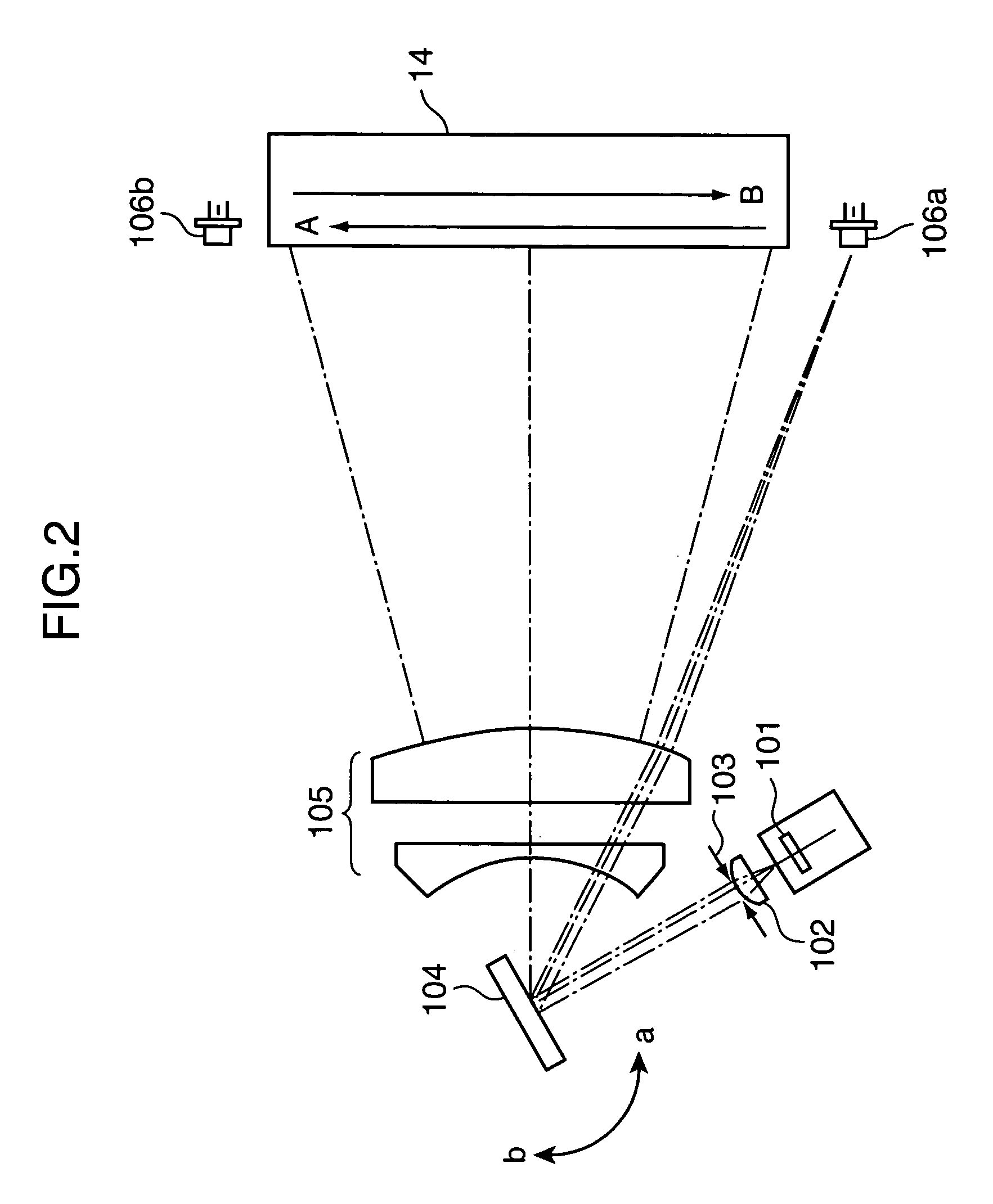
[0017]The photosensitive drum 14 is a cylindrical member, and is rotated in the clockwise direction in FIG. 1 by receiving a driving force from an unillustrated motor. The charger 13 substantially uniformly charges the surface of the photosensitive drum 14. The laser scanner 11 is provided with a light source such as a laser diode, and forms an electrostatic latent image corresponding to image data by emitting a light signal in accordance with the image data onto the surface of the photosensitive drum 14, which is substantially uniformly charged by the char...


PUM


Abstract

A printer has a laser emitter for emitting a laser beam to irradiate a surface of a photosensitive member; a reflector for reflecting the laser beam to a target position on the photosensitive member; a driver for moving the reflector; a resolution changeover designation acceptor for accepting a designation on a low resolution or a high resolution as a resolution for image formation; and an emission controller for controlling the laser emitter to emit the laser beam along a scanning line in a forward direction or a scanning line in a backward direction defined by the movement of the reflector driven by the reflective mirror driver if the designated resolution is the low resolution, and for controlling the laser emitter to emit the laser beam along the scanning line in the forward direction and the scanning line in the backward direction if the designated resolution is the high resolution.

Description

BACKGROUND OF THE INVENTION[0001]1. Field of the Invention[0002]The present invention relates to an image forming apparatus for forming an image with use of laser light, and an image forming method for use in the image forming apparatus.[0003]2. Description of the Related Art[0004]Heretofore, there has been generally used a laser scanner equipped with a rotary polygon mirror in an image forming apparatus such as a copier, a printer, or a fax. In the image forming apparatus, the interval of scanning lines can be decreased by increasing the rotation number of the rotary polygon mirror, which enables to increase the number of scanning lines per unit time, thereby enhancing the resolution in the sub-scanning direction. Also, the resolution in the sub-scanning direction can be enhanced by decreasing the moving speed i.e. the rotating speed of a photosensitive member. Japanese Unexamined Patent Publication No. 09-52387 recites an image forming apparatus equipped with a galvano mirror in p...

Claims


Application Information

Patent Timeline
Patent Type & Authority Patents(United States)
IPC IPC(8): G02B26/08B41J27/00
CPCG02B26/105Y10S359/90
Inventor OKADA, MASANORI
Owner KYOCERA DOCUMENT SOLUTIONS INC
Learn More