
Image forming apparatus and image forming method

a technology which is applied in the field of image forming apparatus and image forming method, can solve the problems of color displacement, noise increase, and displacement of the position of the image to be formed on the recording sheet, so as to eliminate the control of increasing and reduce the effect of color displacement and noise increas

Inactive Publication Date: 2008-03-25
KYOCERA DOCUMENT SOLUTIONS INC
View PDF4 Cites 0 Cited by
  • Summary
  • Abstract
  • Description
  • Claims
  • Application Information

AI Technical Summary

Benefits of technology

The present invention provides an image forming apparatus that overcomes the problems of increased noise, shortened motor life, and increased radiation in the prior art. The apparatus includes a laser emitter, reflector, driver, setter, and emission controller. The reflector moves the laser beam along a scanning line on the surface of a photosensitive member in a direction for scanning. The setter selectively sets the scanning line by emitting the laser beam in both forward and backward directions. The emission controller controls the laser emitter to emit the laser beam along the scanning line in the direction set by the setter. This arrangement reduces the displacement between the actual scanning line and the targeted scanning line, resulting in less positional and color displacement. It also eliminates the need for increasing the rotation number of a rotary polygon mirror, which has drawbacks such as increased noise and shortened motor life.

Problems solved by technology

In the image forming apparatus, there is likelihood that the position of an image to be formed on a recording sheet may be displaced from where the image should be formed in a sub-scanning direction due to an attachment error regarding the position of a laser light source or the like.
This leads to a displacement that relative scanning positions are displaced between the respective colors, which may cause a color displacement due to the displacement of the relative scanning positions between the respective colors.
In the image forming apparatus designed to increase the rotation number of the rotary polygon mirror, a noise may be increased by increasing the rotation number, or the useful life of a motor may be shortened, or use of a costly motor may be needed.
Also, if the rotation number of the rotary polygon mirror is increased, a clock for outputting image data may be increased, which may lead to unduly increase of radiation.

Method used


Image

  • Image forming apparatus and image forming method
  • Image forming apparatus and image forming method
  • Image forming apparatus and image forming method

Examples


Embodiment Construction

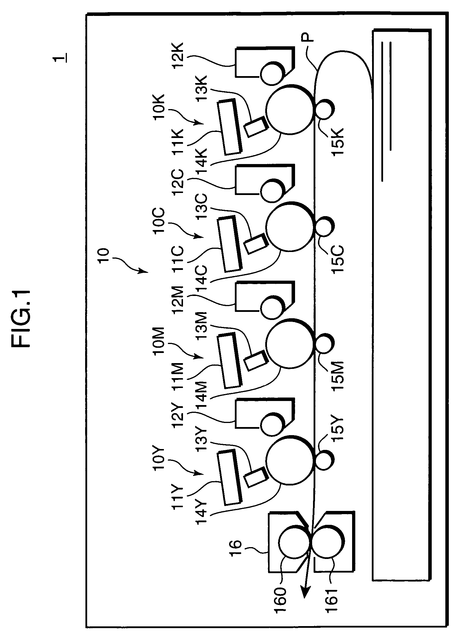
[0021]In the following, an embodiment of the invention is described referring to the drawings. FIG. 1 is a block diagram showing a mechanical construction of a printer 1 as an example of an image forming apparatus in accordance with an embodiment of the invention. The printer 1 includes an image forming assembly 10, and a fixing unit.16 as mechanical components for image formation.

[0022]The image forming assembly 10 has image forming units 10Y, 10M, 10C, and 10K for forming toner images of yellow (Y), magenta (M), cyan (C), and black (K), respectively. Since the image forming units 10Y, 10M, 10C, and 10K have identical constructions to each other, the construction of the image forming unit is described by taking an example of the image forming unit 10K, and description on constructions of the image forming units 10Y, 10M, and 10C will be omitted herein.

[0023]The image forming unit 10K has a laser scanner 11K, a developer 12K, a charger 13K, a photosensitive drum 14K, and a transfer ...


PUM


Abstract

A printer has a laser emitter for emitting a laser beam to irradiate a surface of a photosensitive member; a reflector, disposed at a position on a laser beam path defined by the laser emitter and the photosensitive member, for reflecting the laser beam emitted by the laser emitter to direct the reflected laser beam to a target position on the surface of the photosensitive member; a reflective mirror driver for reciprocating the reflector in such a manner that the laser beam travels along a scanning line on the surface of the photosensitive member in a direction for scanning; and an emission controller for controlling the laser emitter to selectively emit the laser beam along the scanning line in the forward direction or the backward direction defined by the movement of the reflector driven by the reflective mirror driver.

Description

BACKGROUND OF THE INVENTION[0001]1. Field of the Invention[0002]The present invention relates to an image forming apparatus for forming an image with use of laser light, and an image forming method for use in the image forming apparatus.[0003]2. Description of the Related Art[0004]Heretofore, there has been generally used a laser scanner equipped with a rotary polygon mirror in an image forming apparatus such as a copier, a printer, or a fax. In the image forming apparatus, there is likelihood that the position of an image to be formed on a recording sheet may be displaced from where the image should be formed in a sub-scanning direction due to an attachment error regarding the position of a laser light source or the like. In such a case, the positional displacement in the sub-scanning direction can be corrected in the unit of scanning line by intentionally shifting an output of laser light by the distance corresponding to an appropriate number of scanning lines in the sub-scanning ...

Claims


Application Information

Patent Timeline
Patent Type & Authority Patents(United States)
IPC IPC(8): H01J3/14B41J15/14B41J2/455B41J2/47G02B26/08G02B7/04
CPCG02B26/127H04N1/1135H04N1/12H04N2201/0082
Inventor OKADA, MASANORI
Owner KYOCERA DOCUMENT SOLUTIONS INC
Learn More