
Image forming apparatus

a color image and forming apparatus technology, applied in the field of tandemstyle color image forming apparatus, can solve the problems of increasing the number of times the polygon motor is driven, the useful life of the polygon motor is also affected by the number of times it is driven, and the power consumption is substantial, so as to achieve high-quality color images and extend the useful life of the motor

Inactive Publication Date: 2007-03-20
KONICA MINOLTA BUSINESS TECH INC
View PDF4 Cites 0 Cited by
  • Summary
  • Abstract
  • Description
  • Claims
  • Application Information

AI Technical Summary

Benefits of technology

"The present invention is an image forming apparatus that can extend the lives of its motors and produce high-quality color images. It includes multiple image forming units, each with a polygon mirror that reflects the writing light and performs monochrome and color image formation. The apparatus has a rotation controller that controls the rotation of the polygon mirrors of the image forming units. During a monochrome image formation session, the rotation controller carries out steady rotation control for the polygon mirrors of the image forming units used for color image formation but not for monochrome image formation. The apparatus also has a color determination means that can determine if the image data is color image data and change the rotation controller's control accordingly. This ensures that the polygon mirrors are rotating at a steady rate when color image formation begins. Overall, the image forming apparatus provides high-quality color images while extending the lives of its motors."

Problems solved by technology

In an image forming apparatus of this type, because the speed of rotation of the incorporated polygon mirrors has increased with the increase in the image forming speed of the apparatus, the amount of power consumption is substantial.
However, while image forming apparatuses of the conventional art described above are designed so as to reduce the period during which the polygon motors are driven, the useful life of a polygon motor is also affected by the number of times it is driven.
In other words, the problem exists that repeatedly starting and stopping a polygon motor depending on whether it is needed for image formation increases the number of times it is driven.
If image formation is begun before a stable rate of rotation is reached, deterioration in image quality such as color shift may result.

Method used


Image

  • Image forming apparatus
  • Image forming apparatus
  • Image forming apparatus

Examples


Embodiment Construction

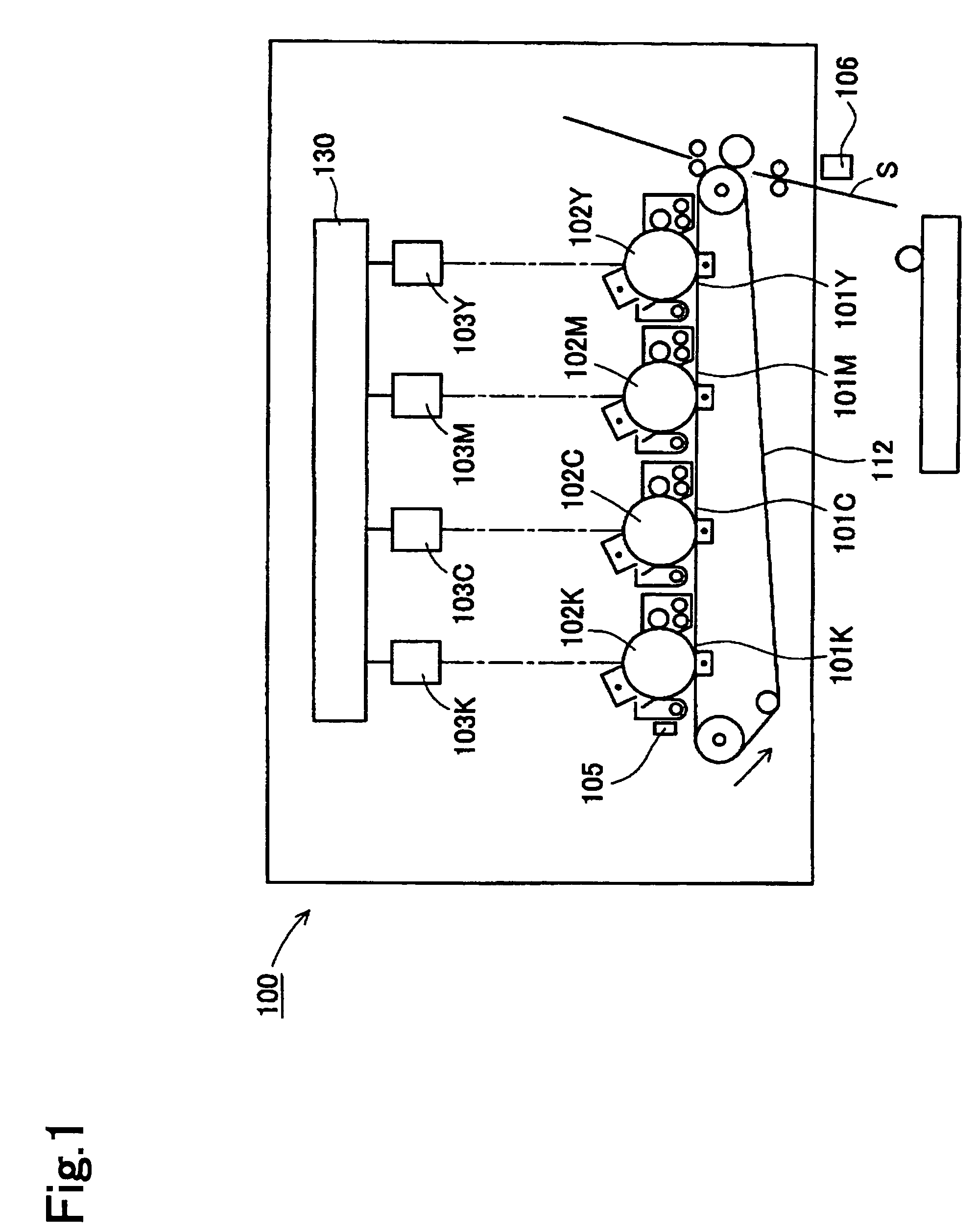
[0033]The best embodiment of the present invention is described in detail below with reference to the attached drawings. This embodiment comprises a tandem-style color printer in which the present invention is applied.

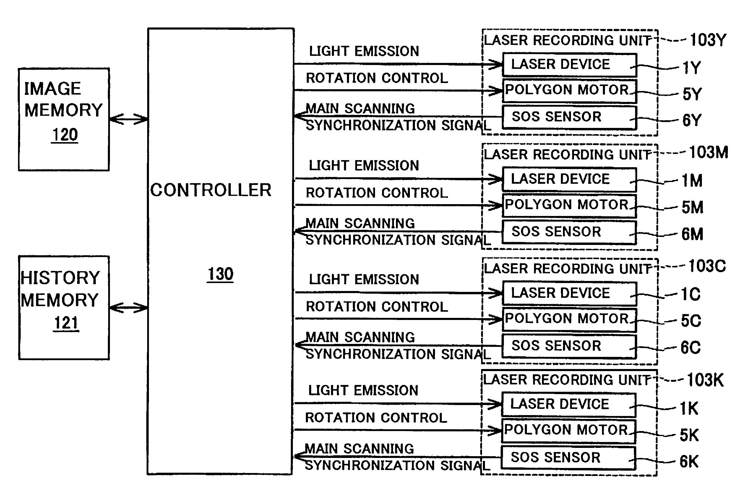
[0034]The color printer 100 of this embodiment includes image forming units 101Y, 101M, 101C, 101K of various colors disposed parallel to one another in this sequence, as shown in FIG. 1. Each of the image forming units 101Y, 101M, 101C, 101K has a photoreceptor drum 102Y, 102M, 102C, 102K, a laser recording unit 103Y, 103M, 103C, 103K and other peripheral devices (including a charger, a developing device, a transfer device and a cleaner). The color printer 100 also includes a resist sensor 105, a TOD sensor 106, a transfer belt 112 and a controller 130.

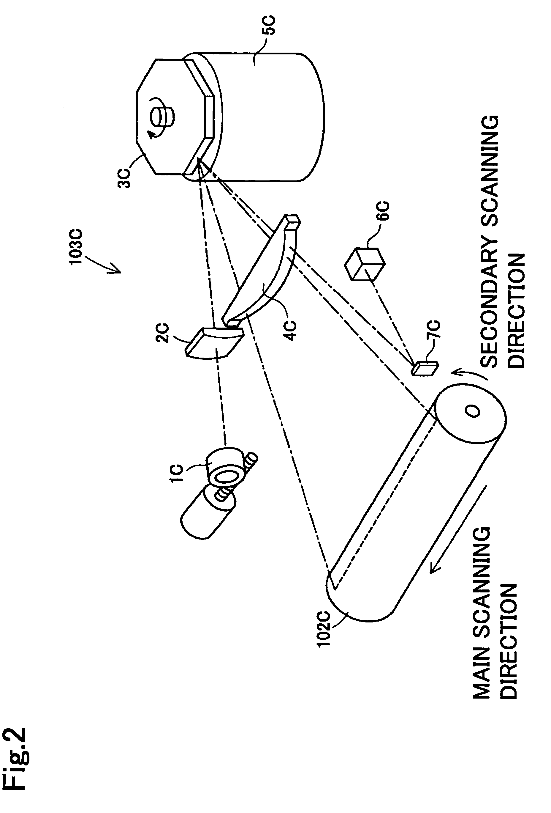
[0035]The image forming units 101Y, 101M, 101C, 101K form images on the transfer belt 112. The laser recording units 103Y, 103M, 103C, 103K irradiate the photosensitive layers of the photoreceptor drums 102Y, 102M, 102C...


PUM


Abstract

The present invention provides a tandem-style image forming apparatus that has multiple image forming units and a controller that controls the rotation of the polygon mirrors of the image forming units, wherein during image formation, the controller performs steady rotation control for the polygon mirrors of the image forming units used for image formation, and where a color image forming session is performed after a monochrome image formation session is completed, the controller performs steady rotation control for polygon mirrors of the image forming units used for color image formation but not for monochrome image formation a prescribed period of time prior to the commencement of image formation by such image forming units, thereby extending the useful lives of the motors that drive the polygon mirrors and producing high-quality color images.

Description

CROSS-REFERENCE TO RELATED APPLICATIONS[0001]This application is based on application(s) No. 2004-41623, filed in Japan on the content of which are hereby incorporated by reference.BACKGROUND OF THE INVENTION[0002]1. Field of the Invention[0003]The present invention relates to a tandem-style color image forming apparatus, and more particularly, to an image forming apparatus that forms a color image using multiple optical scanning devices.[0004]2. Description of the Related Art[0005]Tandem-style color image forming apparatuses that have multiple optical scanning devices and form images of various colors using these optical scanning devices are now in general use. For example, one type of commonly used image forming apparatus has photoreceptor units corresponding to cyan (C), magenta (M), yellow (Y) and black (K), each of which includes a corresponding laser device, and forms a color image by transferring onto paper or onto an intermediate transfer unit images of the various colors su...

Claims


Application Information

Patent Timeline
Patent Type & Authority Patents(United States)
IPC IPC(8): G03G15/01B41J2/435G03G13/01G03G13/04G03G15/04B41J2/44B41J2/385B41J2/47G02B26/12G03G21/00G03G21/14
CPCG02B26/122B41J2/473
Inventor WATANABE, YOSHIKAZUHAMADA, TAKATOSHIOBAYASHI, MAKOTOMARUTA, SYUJI
Owner KONICA MINOLTA BUSINESS TECH INC
Learn More