Electrical wiring device

a technology of ground fault and circuit interrupter, which is applied in the direction of emergency protective circuit arrangement, electrical equipment, etc., can solve the problems of inherently more difficult to prevent the problem of a defective solenoid driving device, the inoperable interrupter device while electrical

Inactive Publication Date: 2006-11-07
PASS SEYMOUR
View PDF21 Cites 49 Cited by
  • Summary
  • Abstract
  • Description
  • Claims
  • Application Information

AI Technical Summary

Problems solved by technology

Historical problems with these protective devices include the possibility of line / load miswiring in the field by an installer or the eventual failure of the solenoid driving device, typically a silicon controlled rectifier, which causes the interrupter device to become inoperable while electrical power is still present, even under hazardous ground fault conditions.
Preventing the problems associated with a defective solenoid driving device is inherently more difficult.

Method used


Image

  • Electrical wiring device
  • Electrical wiring device
  • Electrical wiring device

Examples


Embodiment Construction

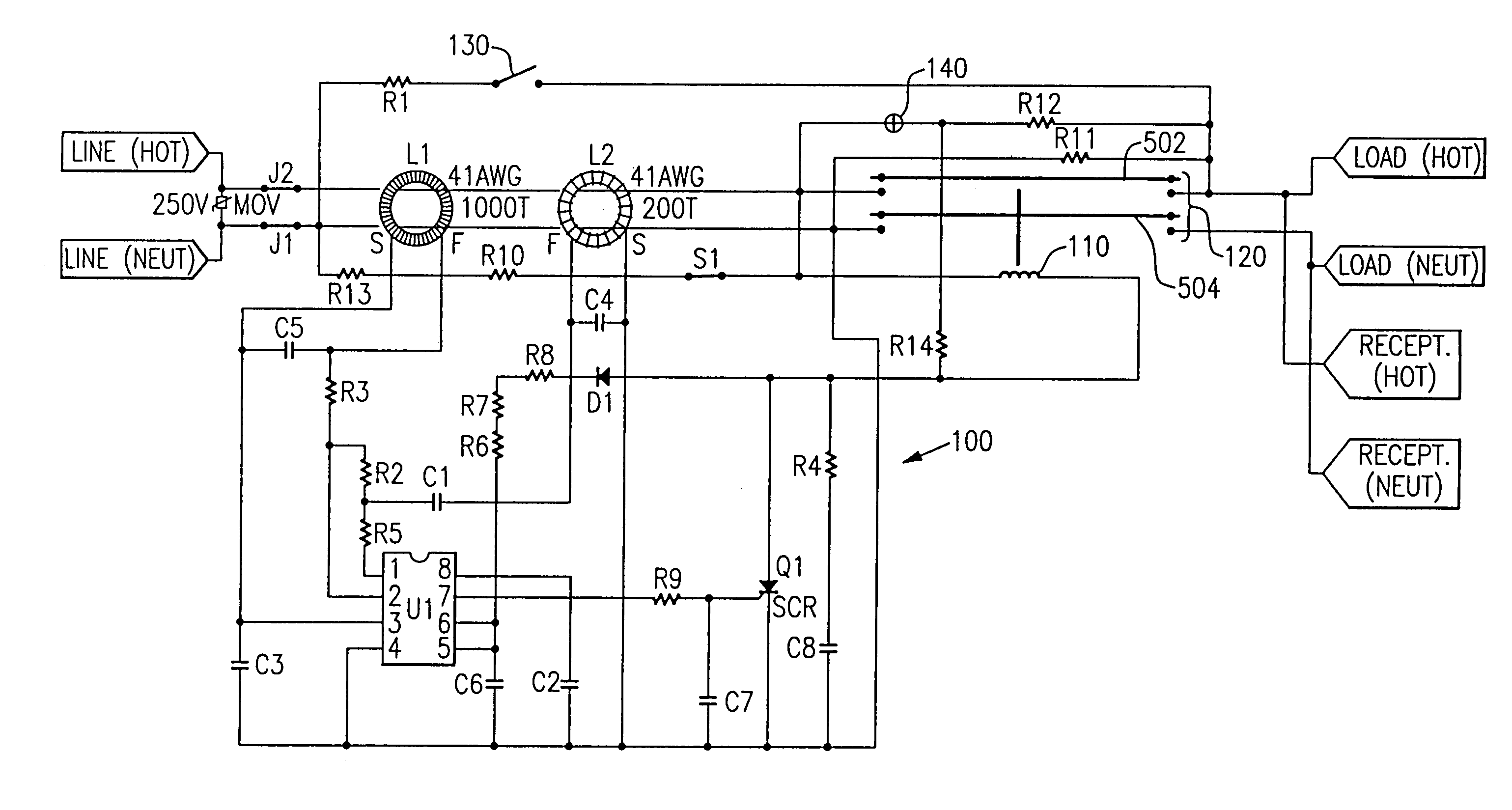
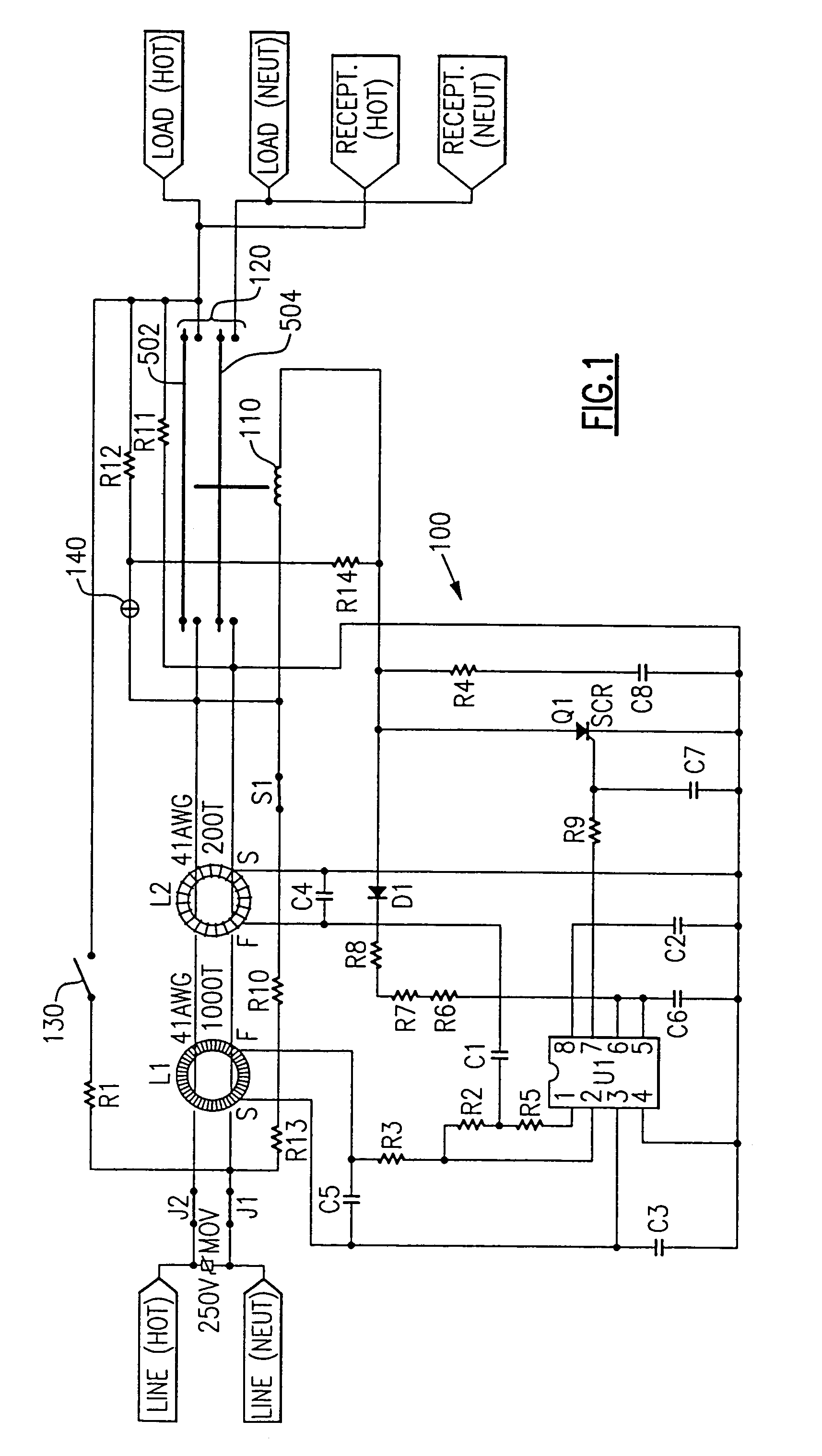
[0021]Referring to FIG. 1, a GFCI circuit is shown generally at 100. When a differential transformer L1 senses unequal amounts of current flowing in the hot and neutral conductors due to a ground fault condition, circuit 100 causes a breaker coil 110 to activate, opening circuit interrupting mechanism 120. Circuit interrupting mechanism 120 conventionally includes hot and neutral bus bars 502, 504 that make and break contact with the hot and neutral power lines, respectively, via contacts located on both the bus bars and power lines at the four contact points. A test button 130 induces a simulated ground fault when pushed in and causes breaker coil 110 to activate.

[0022]This improved GFCI contains two unique features that address the problems noted in the background section. The first is a miswire circuit which uses a fault resistance R10, R13 creating a differential current on the primary of the differential current transformer L1 that exceeds the level of differential current that...


PUM


Abstract

The present invention is directed to an electrical wiring protection device that includes a housing assembly having a hot line terminal, a neutral line terminal, a hot load terminal, and a neutral load terminal partially disposed therein. A miswire detection circuit is coupled to the hot line terminal, the neutral line terminal, the hot load terminal, and the neutral load terminal. The miswire detection circuit is configured to generate a miswire fault condition when AC power is coupled to the hot load terminal and the neutral load terminal and open circuit when AC power is coupled to the hot line terminal and neutral line terminal. A fault detection circuit is coupled to the miswire detection circuit. The fault detection circuit is configured to generate a fault detection signal in response to detecting at least one fault condition. The at least one fault condition including the miswire fault condition. An interrupting contact assembly is connected to the fault detection circuit. The interrupting contact assembly includes interrupting contacts that provide electrical continuity between the hot line terminal and the hot load terminal, and the neutral line terminal and the neutral load terminal in a reset condition. The interrupting contact assembly is also configured to open the interrupting contacts in response to receiving the fault detection signal.

Description

CROSS-REFERENCE TO RELATED APPLICATIONS[0001]This is a continuation of U.S. patent application Ser. No. 09 / 971,525 filed on Oct. 5, 2001 now U.S. Pat. No. 6,856,498, which is a continuation of Ser. No. 09 / 718,003 now U.S. Pat. No. 6,522,510 filed Nov. 21, 2000, the content of which are relied upon and incorporated herein by reference in its entirety, and the benefit of priority under 35 U.S.C. §120 is hereby claimed.FIELD OF THE INVENTION[0002]This invention pertains to the field of ground fault circuit interrupter devices, and in particular, to a ground fault interrupter device with an indicator lamp and protective circuit powered from the hot bus bar of the interrupting contacts.BACKGROUND OF THE INVENTION[0003]Protective devices such as ground fault circuit interrupters (GFCIs) are well known in the art. Their intent is and always has been to protect the electrical power user from electrocution when hazardous ground fault currents are present.[0004]Historical problems with these ...

Claims


Application Information

Patent Timeline
Patent Type & Authority Patents(United States)
IPC IPC(8): H02H9/08
CPCH02H3/338
Inventor FINLAY, DAVID A.
Owner PASS SEYMOUR
Why Eureka
Try Eureka