Calibrated sensor and method for calibrating same

a sensor and sensor technology, applied in the field of calibration sensors and methods, can solve the problems of not always practical and many physical quantities cannot be directly measured, and achieve the effect of improving sensor performance, reducing sensor cost, and increasing sensor cos

Inactive Publication Date: 2006-11-07
CORRELATED SOLUTIONS
View PDF7 Cites 28 Cited by
  • Summary
  • Abstract
  • Description
  • Claims
  • Application Information

AI Technical Summary

Benefits of technology

[0008]An important advantage of this invention is the lack of a need for specific planar objects or special equipment to calibrate a sensor. This advantage frees up the user to use whatever objects and equipment is convenient for calibrating a sensor according to the present method.
[0009]Another advantage of the present method is that it is not based on or derived from a particular type of sensor. This permits the calibration of the type of sensors that may be producing a non-linear output.
[0010]Still another important advantage of this method is that it allows sensors that are of lesser quality to be used in circumstances where better quality sensors would otherwise have

Problems solved by technology

A problem familiar to every engineer is that many physical quantities cannot be measured directly.
If g(x) is not well characterized by a low-order function, a direct calibration will r

Method used


Image

  • Calibrated sensor and method for calibrating same
  • Calibrated sensor and method for calibrating same
  • Calibrated sensor and method for calibrating same

Examples


Embodiment Construction

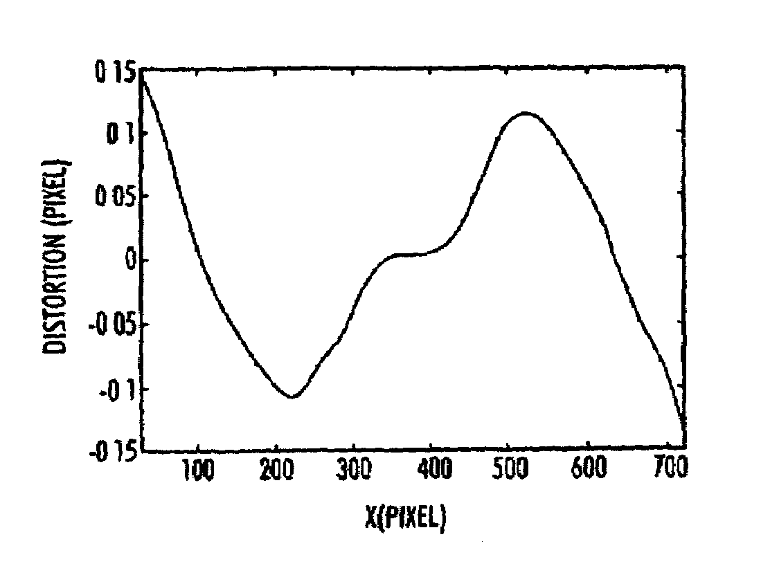
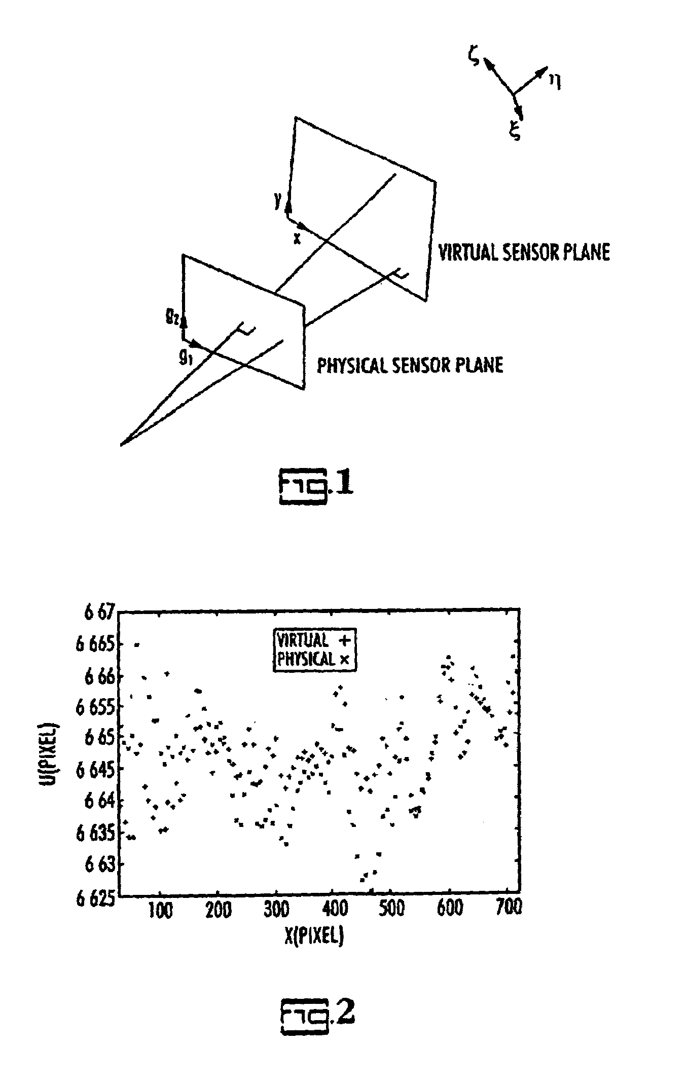
[0019]The present invention will be described in connection with an optical sensor, partly for convenience and partly because the present invention works well with optical sensors, but the present invention is not limited to optical sensors. As noted previously, the term “senor” is intended to include any combination of imaging elements and physical sensing elements such as photodiode arrays, as well as a great many transducers. Any measurement system that would inherently have distortion, that is, non-linear response, can benefit from the present method.

[0020]The present method requires use of the sensor to obtain several images of a planar object; each image is obtained following a translation relative to the object by a small distance from the preceding one, as a prerequisite to deriving the calibration function. These translations must be (1) in the same plane as the planar object and (2) non-parallel, and preferably orthogonal. Non-parallel movements have orthogonal components ...


PUM


Abstract

For an optical sensor, a simple approach to obtain a mapping function that transforms sensor coordinates of a generic imaging system to coordinates of a virtual, projective camera. The sensor plane of this virtual camera is established using a planar calibration object and does not require known features on the object. Two in-plane motions are sufficient to establish the distortion-free virtual camera. The sensor plane of the virtual projective camera is used to calibrate all subsequent images obtained by the optical sensor. For a generic sensor, the present method is a simple approach to obtain a mapping function that transforms sensor measurements into a virtual sensor system. The virtual sensor system is established using a uniform bias. The virtual sensor system is used to calibrate all subsequent measurements obtained by the sensor.

Description

CROSS-REFERENCE TO RELATED APPLICATIONS[0001]Not applicable.STATEMENT REGARDING FEDERALLY SPONSORED RESEARCH OR DEVELOPMENT[0002]Not applicable.REFERENCE TO A MICROFICHE APPENDIX[0003]Not applicable.BACKGROUND OF THE INVENTION[0004]A problem familiar to every engineer is that many physical quantities cannot be measured directly. Instead, the response g(x) of a measurement system, such as a sensor, to physical quantities x is measured. Here, the term “sensor” refers to any system with response g(x) to a physical quantity x. For an optical system, the “sensor” may be any combination of lenses, mirrors, prisms, filters and physical sensing elements that comprise the imaging system. Thus, the relationship between the physical quantity and the response function for the sensor may not be linear. For best results, the sensor must be calibrated by linearizing the reponse to produce the calibrated output. Calibration requires the determination of the inverse of g.[0005]Typically, calibration...

Claims


Application Information

Patent Timeline
IPC IPC(8): G06K9/64G06K9/32G06K9/68
CPCG06T7/0018G06T7/80
Inventor SCHREIER, HUBERT W.SUTTON, MICHAEL A.
Owner CORRELATED SOLUTIONS
Why Eureka
Try Eureka