Eureka AIR delivers breakthrough ideas for toughest innovation challenges, trusted by R&D personnel around the world.

Odd offset fabrication kit

Inactive Publication Date: 2006-11-14
MITCHELL IRVIN
View PDF10 Cites 8 Cited by
  • Summary
  • Abstract
  • Description
  • Claims
  • Application Information

AI Technical Summary

Benefits of technology

[0009]Therefore, it is a principal object of the present invention to aid pipe instructors, fabricators, designers and engineers with a tool to simplify the method of odd offsets without the use of formulas and calculations.
[0010]It is a further object of the present invention to offer answers for solutions, without the calculation of formulas, and to eliminate errors from calculations.
[0011]It is a further object of the present invention to simplify the process for use by common craftsman, and eliminating valuable time used for researching solutions.

Problems solved by technology

During this time he has encountered challenges that caused much valuable time searching for solutions to solve problems in the area of odd offsets.

Method used


Image

  • Odd offset fabrication kit
  • Odd offset fabrication kit
  • Odd offset fabrication kit

Examples


Embodiment Construction

[0030]FIGS. 1–8 illustrate the preferred embodiment of the apparatus of the present invention, while FIGS. 9 through 17 illustrate additional embodiments of the present invention.

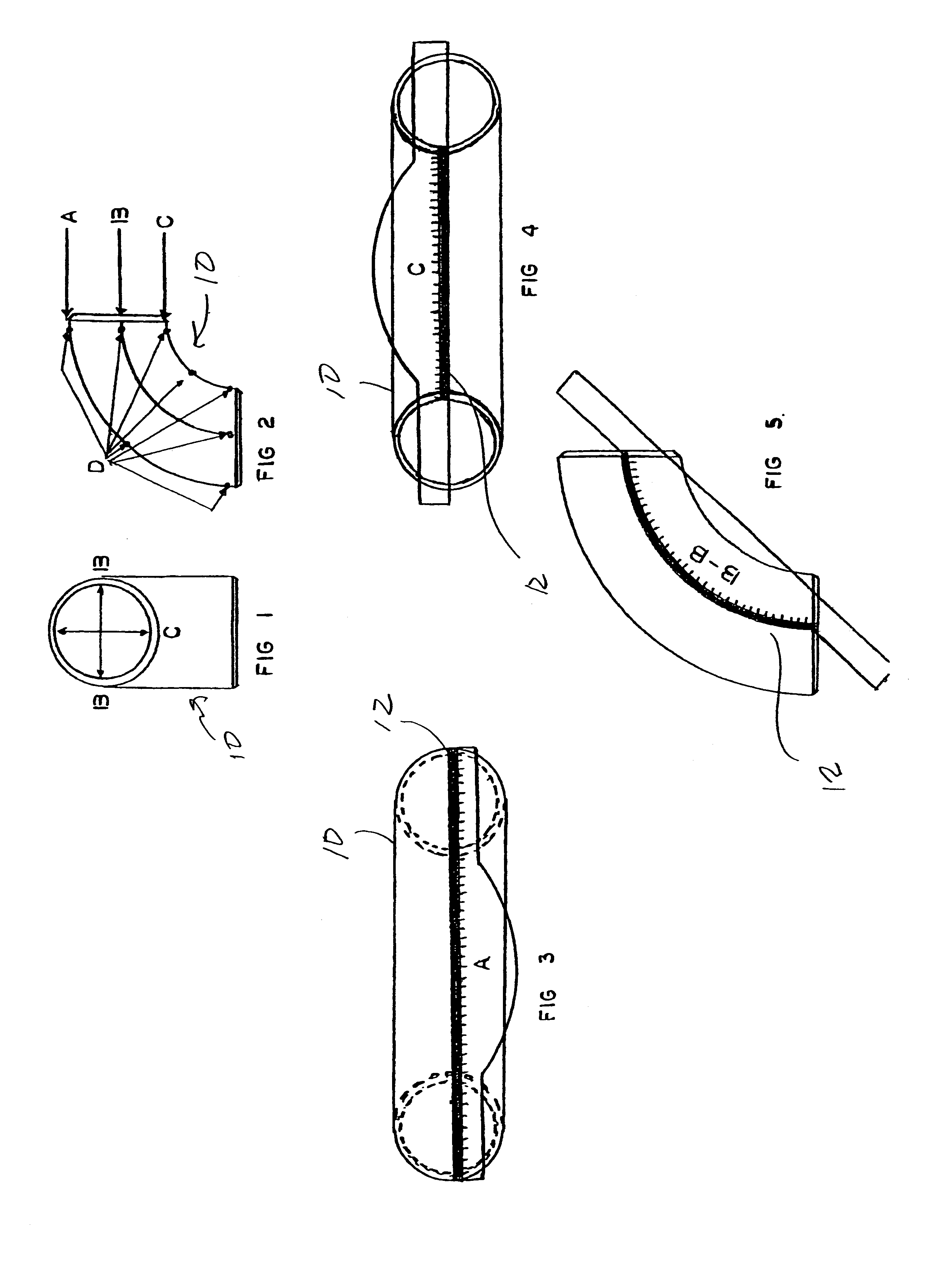
[0031]As seen first in FIG. 1, there is provided the front view of ell 10, having a first outside radius A, a centerline radius B, and an inside radius c. In FIG. 2, the side view of ell 10 is shown, having the outside radius A, the centerline radius B, and the inside radius C, and further illustrating center line punch marks D. The center marks on inside and outside radius lines A and C, as shown in FIG. 2, should have a minimum of three punch marks, for purposes of straight line layout.

[0032]Turning now to FIG. 3, there is illustrated the configuration of outside radius layout. After the centerline layout, place degree graph 12 using side A on the centerline of outside radius placing the zero degree increment on each end of ell 10, then mark the desired degree.

[0033]As seen in FIG. 4, there is illustrated...


PUM


Abstract

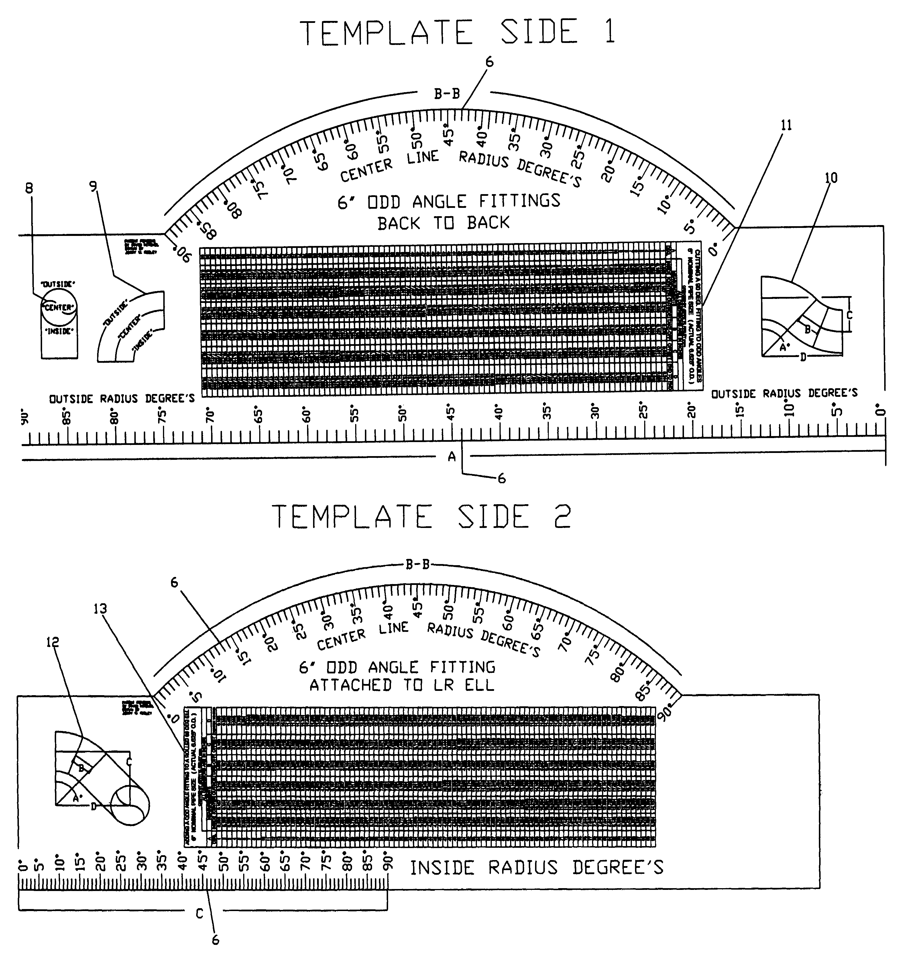
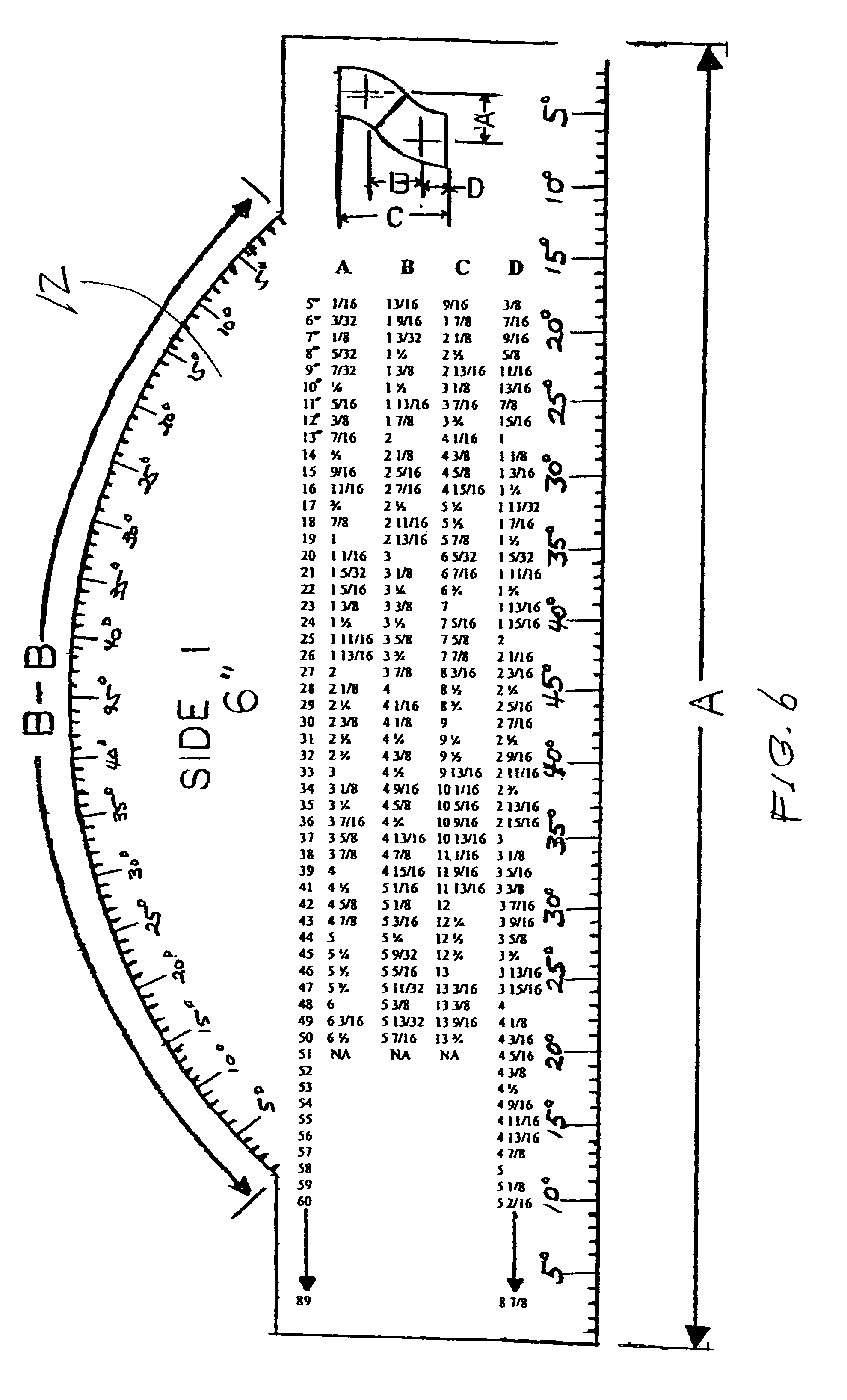
A template that would be created with a given line for outside, centerline and inside radius of ell marked in one degree increments, starting with zero degree from the end of each radius of ell and ending at ninety degrees. Incorporated on the template would be a sketch of back to back odd fittings, with all dimensions given for the offset, end to end and the take off of all dimensions from one to ninety degrees, for odd fittings fabricated from the standard ninety degree ell. The offset, and end to end dimensions, would terminate at ninety degrees. Also incorporated on the template would be a sketch of a ninety degree ell with odd degree fitting attached, with all dimensions given for the offset and the center to end using all degrees from one to ninety.

Description

CROSS-REFERENCE TO RELATED APPLICATIONS[0001]Priority of U.S. Provisional Patent Application Ser. No. 60 / 566,623, filed Apr. 29, 2004, incorporated herein by reference, is hereby claimed.STATEMENT REGARDING FEDERALLY SPONSORED RESEARCH OR DEVELOPMENT[0002]Not applicableREFERENCE TO A “MICROFICHE APPENDIX”[0003]Not applicableBACKGROUND OF THE INVENTION[0004]1. Field of the Invention[0005]The summary of the invention relates to a template or pattern for the layout of odd offsets in pipe fabrication using the standard ninety degree long radius ell. More particularly, the template can be developed in a raw material and on a software program with the capability of printing the template with the use of a plotter.[0006]2. General Background of the Invention[0007]For the past nearly three decades the inventor has been involved in the field of pipe fabrication. During this time he has encountered challenges that caused much valuable time searching for solutions to solve problems in the area ...

Claims


Application Information

Patent Timeline
IPC IPC(8): G01B5/24
CPCG01B3/14G01B3/563
Inventor MITCHELL, IRVIN
Owner MITCHELL IRVIN
Why Eureka
Eureka Blog
Learn More