Vehicle seat heating arrangement

a technology for vehicle seats and heating elements, which is applied in the field of vehicle seat heating arrangements, can solve the problems of only being able to adhere to a particular section of the seat surface, severe injuries, and relatively limited space for mounting of heating elements, and achieves the effect of convenient mounting

Inactive Publication Date: 2006-11-14
KONGSBERG AUTOMOTIVE AB (SE) +1
View PDF17 Cites 137 Cited by
  • Summary
  • Abstract
  • Description
  • Claims
  • Application Information

AI Technical Summary

Benefits of technology

[0014]By means of the invention, several advantages can be accomplished. Firstly, it can be noted that the invention constitutes one single pre-assembled unit which can be easily mounted in a vehicle seat during manufacturing thereof. Furthermore, with a common, integrated unit, its adhesion to the surface of the vehicle seat can be made as large as necessary since the occupant sensor will not need any separate adhesion points. Also, the problem involving a risk that the occupant sensor would slide out of position in relation to the heating element can be eliminated by means of the invention.

Problems solved by technology

This is due to the fact that an airbag for a passenger in the vehicle can cause severe injuries if it is activated when, for example, a rearwards facing child-seat is positioned in front of an airbag, or when a passenger who is not using a safety-belt leans forward at the moment of activation of the airbag.
However, various problem may occur if a seat provided with a heating element as mentioned above were also to be equipped with a separate sensor for detecting the presence of an occupant in said vehicle.
Firstly, it can be noted that the heating element can only be adhered to a particular section of the surface of the seat cushion where the sensor is not mounted.
This allows a relatively limited area for the mounting of the heating element.
Furthermore, there is a risk that the occupant sensor surface will come into contact with adhesion glue which is used for the heating element.
This may cause prebending of the sensor, which in turn may lead to deterioration of the detection signal from the occupant sensor.
Also, such an known arrangement would comprise a large number of components, which would lead to high costs for the seat.
Furthermore, such an arrangement would imply a complex and costly assembly of the seat, which would also lead to higher costs.
Also, there is a risk that the operation of the two components, i.e. the heating element and the occupant sensor, would be interfered since the components are mounted very close to each other.
Also, such an assembly of a heating element and an occupant sensor would imply a risk that the sensor would slide out of position during its lifetime.
Finally, such an assembly of a heating element and an occupant sensor would imply a risk that the heating element would interfere with the operation of the occupant sensor, i.e. the sensor may supply erroneous signals if is is heated.
Consquently, there are various problems involved when trying to combine these two components within the same vehicle seat.

Method used


Image

  • Vehicle seat heating arrangement
  • Vehicle seat heating arrangement
  • Vehicle seat heating arrangement

Examples


Embodiment Construction

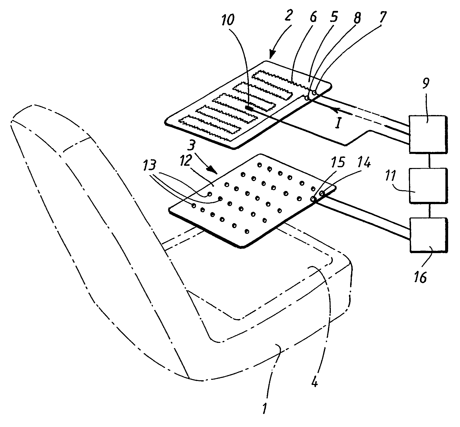
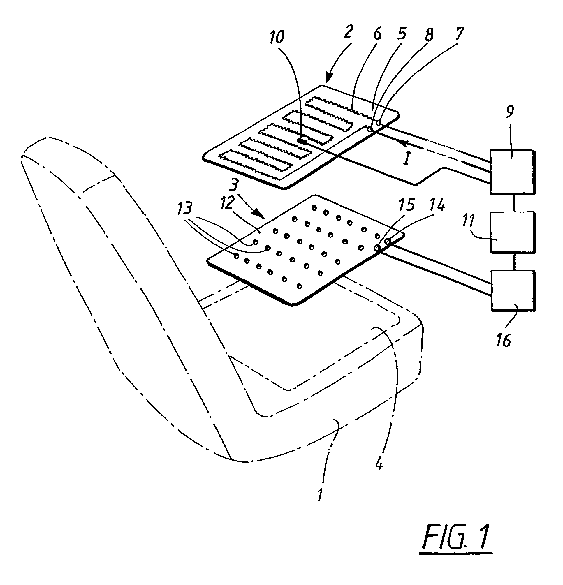
[0020]FIG. 1 shows a schematic and slightly simplified circuit diagram of an arrangement according to the present invention. According to the preferred embodiment, the invention is intended for use in connection with an electrically heatable seat 1 in a vehicle.

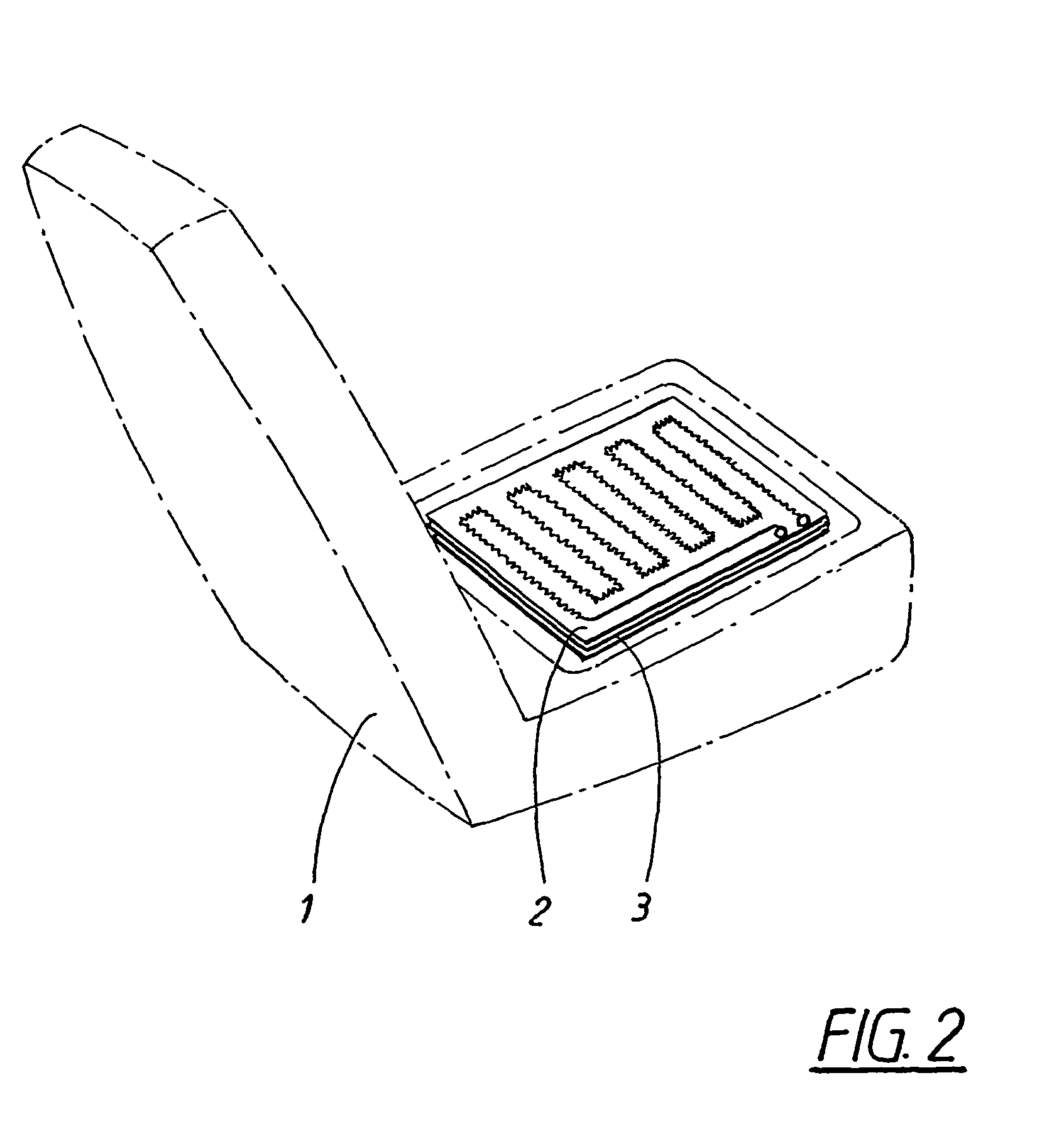
[0021]FIG. 1 shows the main components forming part of the invention, which generally constitutes an integrated heating and occupant presence detection system. According to a preferred embodiment, said arrangement comprises a seat heating device 2 and an occupant presence sensor 3, which in FIG. 1 are shown in a separated manner, but are intended to be assembled and arranged as an integrated component to be placed in a predetermined area 4 in the vehicle seat 1.

[0022]It should be noted that the invention is not limited to any particular type of vehicle seats, but can be used in cars, buses, trucks or other types of vehicles in which a heatable seat can be used.

[0023]The heating device 2 will now be described in detail. The he...


PUM


Abstract

A vehicle seat having a heating device arranged in connection with the vehicle seat and connected to a control unit which includes a current-feeding apparatus for feeding a current to the heating device. The vehicle seat also includes a temperature sensor connected to the control unit for detecting the temperature at the heating device. The control unit is arranged to feed the current if the measured temperature falls below a pre-determined temperature value. An occupant sensor is also provided for detecting the presence of an occupant or an object in the vehicle seat. The occupant sensor is arranged as a single integral unit together with the heating device in the vehicle seat.

Description

TECHNICAL FIELD[0001]The invention relates to a vehicle seat arrangement comprising a heating device arranged in connection with a vehicle seat and connected to a control unit which comprises current feeding means for feeding a current to the heating device in order to heat it, a temperature sensor connected to said control unit for detecting the temperature at said heating device, the control unit being arranged to to feed said current if said measured temperature falls below a predetermined temperature value.[0002]Furthermore, the invention relates to a method for manufacturing a vehicle seat arrangement.BACKGROUND OF THE INVENTION[0003]For reasons of comfort and safety, today's vehicles are often provided with electrically heatable vehicle seats. The driver's seat, as well as the other seats in the vehicle, can be so arranged that they can be heated by means of heating elements in the form of electrically conducting wires which can be placed in each seat in the shape of a heating...

Claims


Application Information

Patent Timeline
Patent Type & Authority Patents(United States)
IPC IPC(8): B60N2/56A47C7/74B60H1/00B60H1/03B60H1/34B60N2/00B60N2/90
CPCB60N2/002B60N2/5685G01G19/4142B60N2/56
Inventor FRISTEDT, TOMMYJOSEFSSON, DANIELRUGGIU, MANUELGALLO, JEAN-FRANCOISLORENZ, HOLGER
Owner KONGSBERG AUTOMOTIVE AB (SE)
Why Eureka
Try Eureka