
Multifrequency power circuit and probe and NMR spectrometer comprising such a circuit

a multi-frequency power circuit and probe technology, applied in the field of precision power supplies, can solve the problems of complex structure, lack of full satisfaction and limitations, and even rigidity of known systems

Active Publication Date: 2006-11-14
BRUKER BIOSPIN
View PDF8 Cites 4 Cited by
  • Summary
  • Abstract
  • Description
  • Claims
  • Application Information

AI Technical Summary

Benefits of technology

[0011]This invention has as its object to propose a simple solution that allows at least some of the above-mentioned drawbacks to be overcome and to exceed some of the mentioned limitations.

Problems solved by technology

These known systems, however, do not provide full satisfaction and exhibit limitations.
The multifrequency power systems currently proposed (see, for example, U.S. Pat. No. 5,861,748) have a very complicated structure (often very difficult to house readily in the narrow cylindrical space that is set aside for that purpose when the probe that contains the coil is received), whereby each power path has to comprise insulation means relative to the influences of the other paths.
Moreover, these known systems are very non-flexible, and even rigid, in terms of frequency variation of different paths or a change in the number of paths (addition of a path or elimination of a path).
Any modification in regard to a path affects all other paths existing within the system and requires an adjustment or changes with regard to the latter, which themselves again have additional repercussions, and in particular because of their dissymmetrical structure.
Finally, owing in particular to production complexity and limited available space, the current multifrequency power systems are limited to at most three different power frequencies and to generally less significant powers.

Method used


Image

  • Multifrequency power circuit and probe and NMR spectrometer comprising such a circuit
  • Multifrequency power circuit and probe and NMR spectrometer comprising such a circuit
  • Multifrequency power circuit and probe and NMR spectrometer comprising such a circuit

Examples


Embodiment Construction

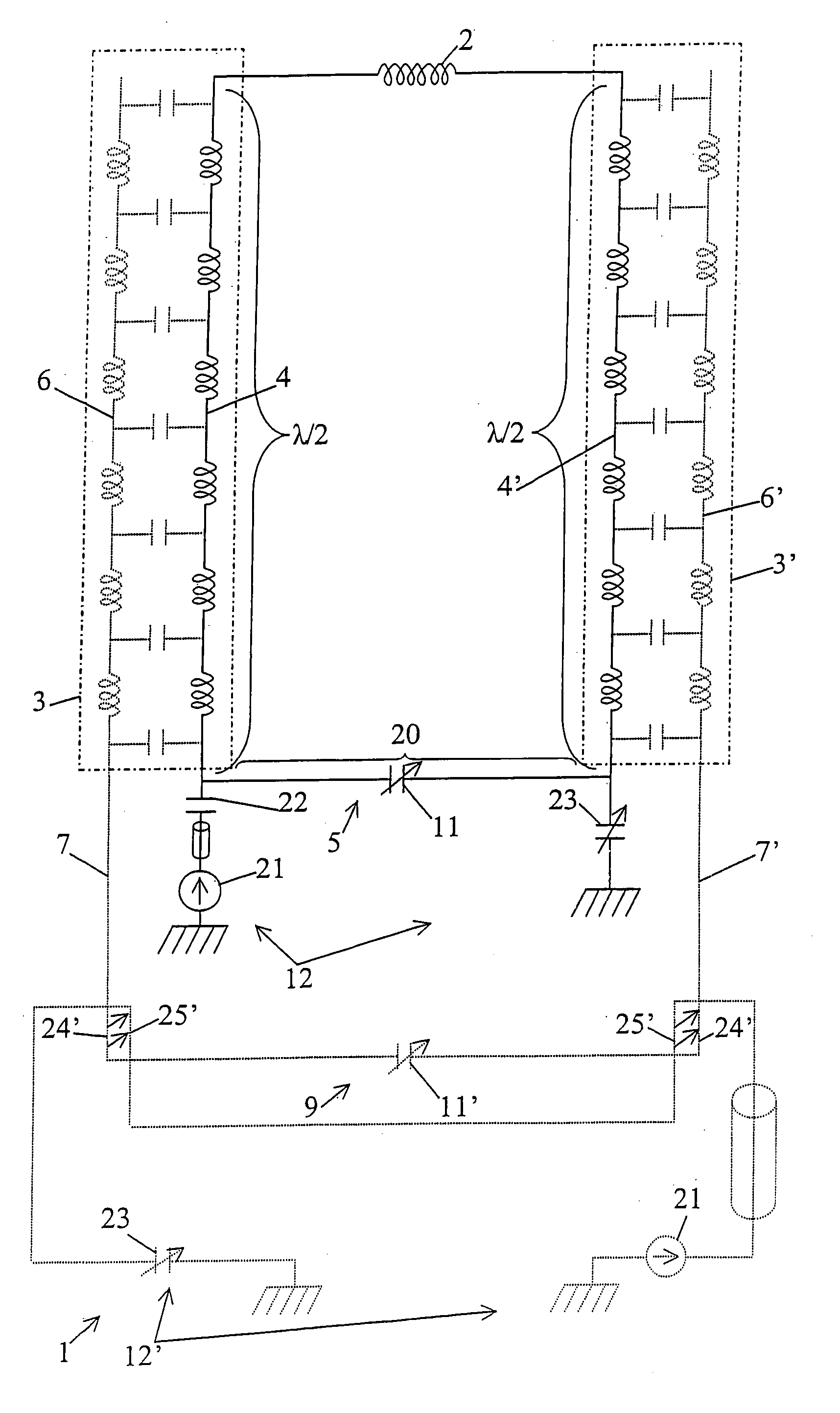
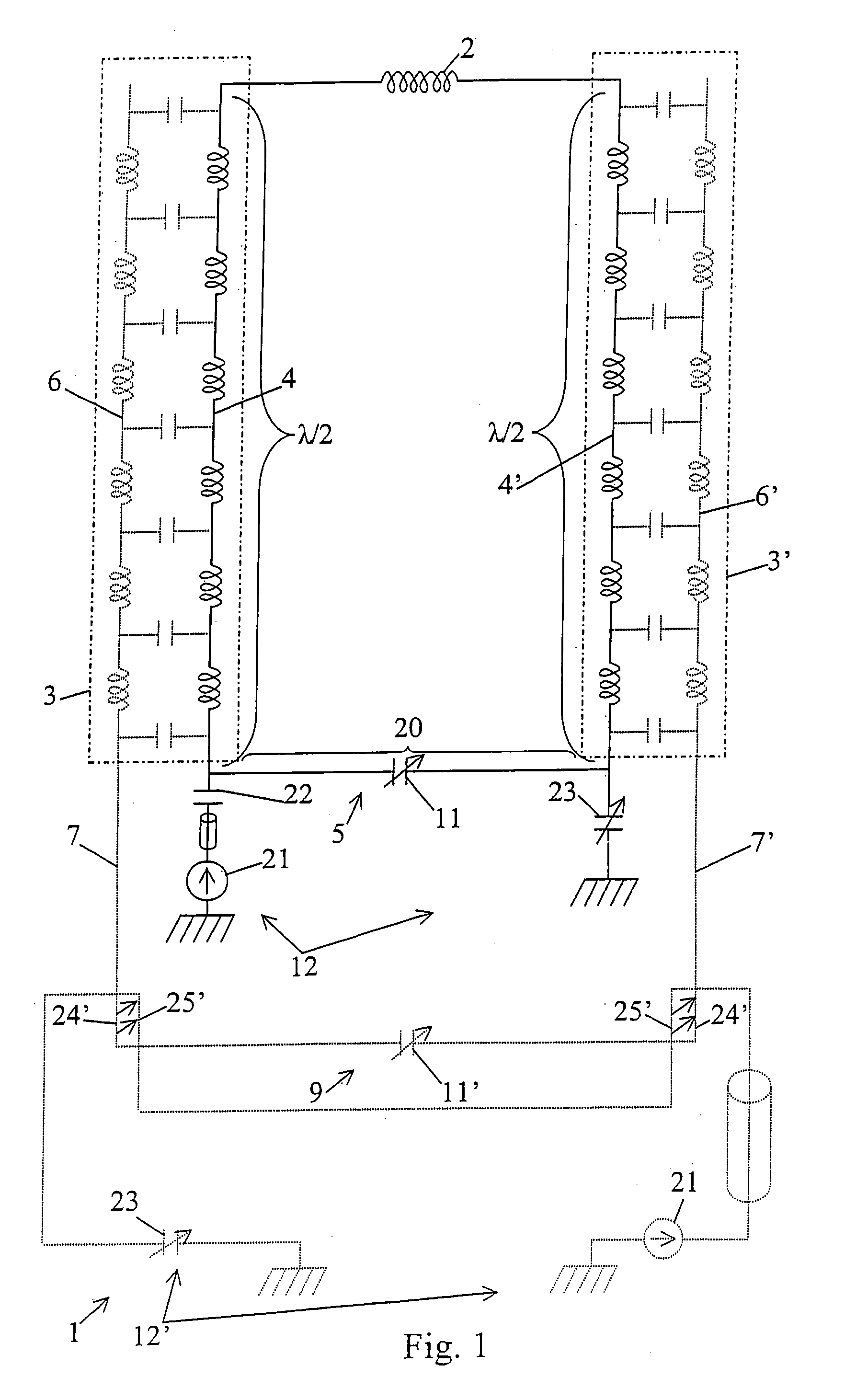
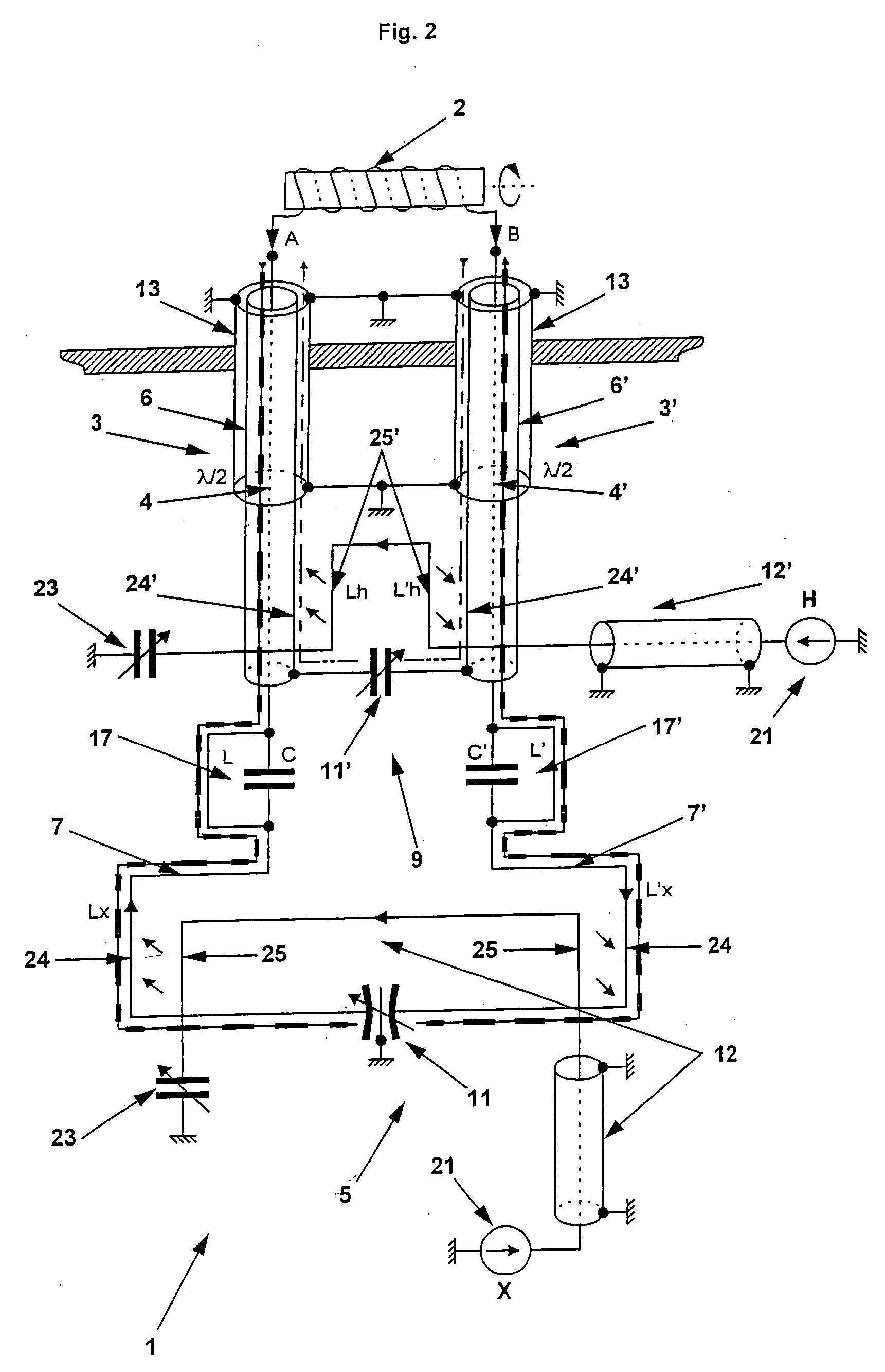
[0024]FIGS. 1 to 5 each show a multifrequency power circuit 1 of a coil 2, in particular of an NMR coil or a sample coil, comprising two power or transmission line segments 3 and 3′, so-called principal line segments, whereby these principal line segments 3, 3′ each comprise at least one conductor segment 4, 4′ that is connected to one of the ends or terminals of said coil 2, and whereby these connected conductor segments 4, 4′ constitute with said coil 2 an oscillating circuit or a first oscillating circuit that has a determined resonance frequency.

[0025]According to the invention, principal power or transmission line segments 3, 3′ consist of controlled-impedance multiconductor line segments that each comprise at least one other conductor segment 6, 6′ that is not connected to coil 2 and that extends into said principal line segment 3, 3′ beside corresponding respectively attached conductor segment 4, 4′ and that exhibits with the latter a capacitive coupling that is distributed a...


PUM


Abstract

A multifrequency power circuit of an NMR coil, includes two power or transmission line segments called principal line segments, each including a segment of a conductor that is attached to the coil, which attached segments together with the coil constitute a first oscillating circuit that exhibits a determined resonance frequency. The principal line segments consist of controlled-impedance multiconductor line segments, each including at least one other conductor segment that is not attached to coil and that extends into the principal line segment beside corresponding respectively attached conductor segment and that exhibits with the latter a capacitive coupling that is distributed along segments located beside or opposite the conductors. These non-attached conductor segments, together with the coil, attached conductor segments and non-attached conductor segments, and optionally with additional power line segments connected to the non-attached conductor segments, form at least one additional oscillating circuit that has a different resonance frequency.

Description

BACKGROUND OF THE INVENTION[0001]This invention relates to the field of precision power supplies, in particular in the nuclear magnetic resonance field, and it has as its object a multifrequency power circuit of a coil, in particular a sample coil, as well as an NMR probe and an NMR spectrometer that comprises such a circuit.DESCRIPTION OF THE RELATED ART[0002]In some applications, it is necessary to use a very specific power, in terms of characteristics and properties of the currents delivered, for circuits that are used in special or extreme circumstances or contexts.[0003]Such is particularly the case for the power of sample or NMR coils, located in the core of the NMR spectrometers.[0004]In particular in the NMR experiments of the solid, it is necessary to use maximum current specifically in the region that receives the sample (subjected to a rotation at several tens of thousands of rotations per second), i.e., in the center of the coil.[0005]Various power systems have already b...

Claims


Application Information

Patent Timeline
Patent Type & Authority Patents(United States)
IPC IPC(8): G01V3/00G01R33/34G01R33/36
CPCG01R33/3635G01R33/34092
Inventor WEISS, MICHELMARTINACHE, LAURENTGONELLA, OLIVIER
Owner BRUKER BIOSPIN
Learn More