Hazardous condition detection system and method and thermostat for use therewith

a technology for hazardous conditions and detection systems, applied in the direction of fire alarms, instruments, heating types, etc., can solve problems such as power loss and communication failur

Active Publication Date: 2006-11-14
INVENSYS SYST INC
View PDF4 Cites 142 Cited by
  • Summary
  • Abstract
  • Description
  • Claims
  • Application Information

AI Technical Summary

Benefits of technology

[0008]An embodiment of the present invention utilizes the thermostat's knowledge of the time of day and date to schedule and initiate a threat detector test event. The user interface allows the consumer to program the day, time, and frequency that the threat detector test should be conducted. One embodiment of the present invention provides a user interface screen that allows the consumer to initiate a test on demand, in addition to the periodic, automatic test schedule programmed therein. In each embodiment, the user interface of the thermostat can display the test results and any other system diagnostic information provided as a result of the testing.
[0010]In a still further embodiment of the present invention, the diagnostic functionality of the thermostat includes initiation of the temporary alarm locate (TAL) function of interconnected hazardous condition detectors. This feature temporarily silences the alarms of interconnected hazardous condition detectors so that the location of the detecting detector may be determined. The user interface may also or alternatively display location information identifying the detecting detector, thereby precluding the need to initiate the TAL function.

Problems solved by technology

Such failure information may be generated as a result of a test failure from one of the automatic or manual tests, or may be a result of a failure to communicate with the thermostat.
Such may simply be a communications failure, or may be the result of a loss of power to the non-communicating or off-line detector, etc.

Method used


Image

  • Hazardous condition detection system and method and thermostat for use therewith
  • Hazardous condition detection system and method and thermostat for use therewith
  • Hazardous condition detection system and method and thermostat for use therewith

Examples


Embodiment Construction

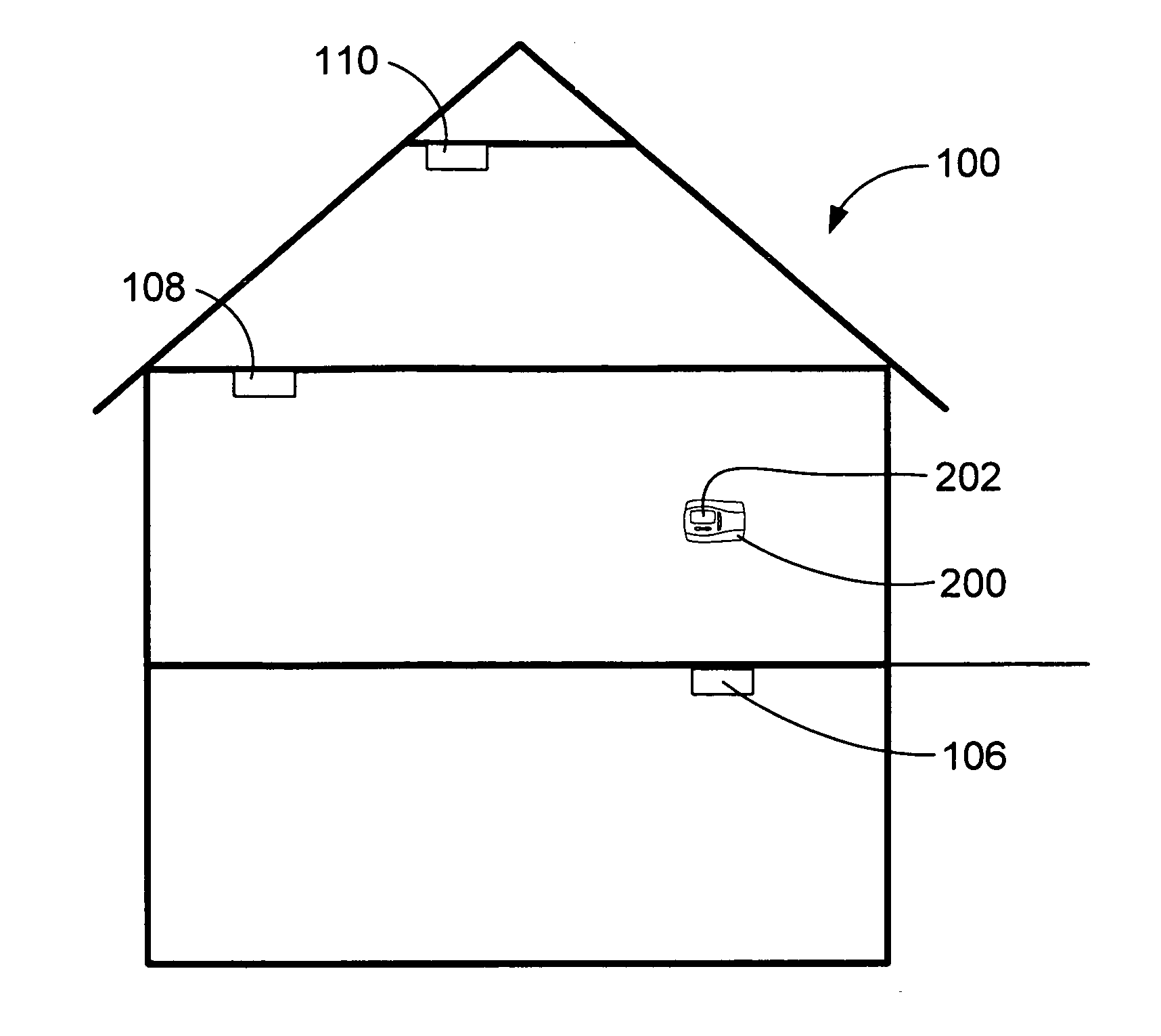
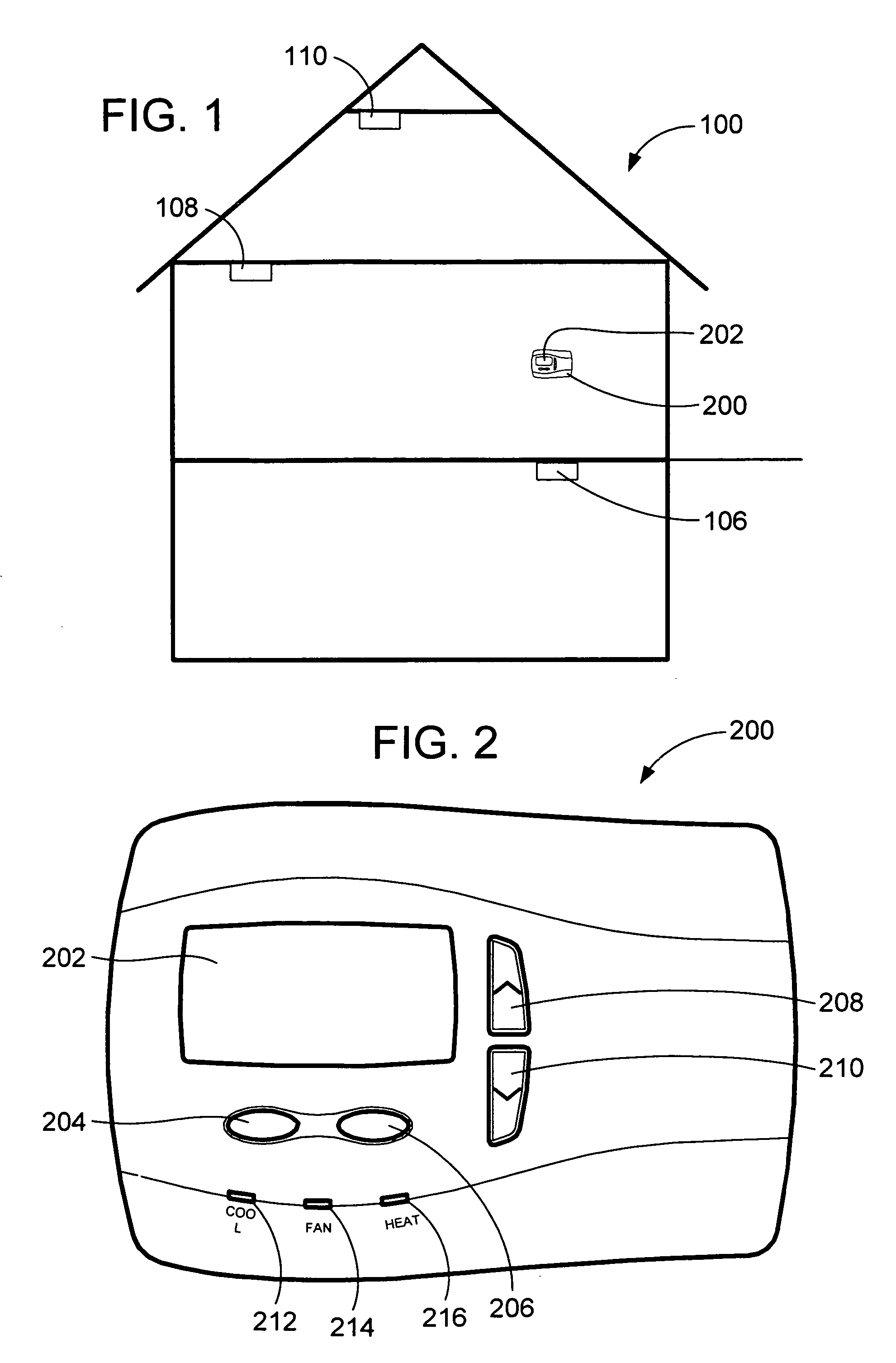
[0016]FIG. 1 illustrates a simplified home environment 100 into which the system of the present invention finds particular applicability. However, one skilled in the art will recognize that the system of the present invention is not limited to a home environment, but may also be installed in a commercial environment, etc. This typical home environment 100 includes an intelligent thermostat 200. As is typical, the thermostat 200 controls heating of the home environment 100 by a furnace (not shown), and possibly cooling of the home environment 100 by the air conditioning system (not shown). The interface to both the furnace and the air conditioning system is typically pre-wired in the home environment 100, although the communications control from the thermostat 200 may also be wireless as desired by providing receiver / transmitter circuitry in the furnace and / or the air conditioning system. Similar receiver / transmitter circuitry is also required in thermostat 200 to provide this commun...


PUM


Abstract

An intelligent thermostat communicates with threat detectors to allow periodic remote testing of the detector. The real-time clock and calendar functions of the thermostat allow the consumer to program the day, time, and frequency of the testing. The thermostat then communicates a test control signal to each of the detectors to initiate the self-test. The communication may be wired or wireless. During testing the thermostat displays a detector test screen. Upon completion of the self-test, the thermostat displays a test results screen for user confirmation. This results screen will indicate that the test passed or failed along with any diagnostic information provided by the detector. The thermostat also provides a test initiation screen from which the consumer may initiate a detector self-test manually. Loss of communications with a detector is also communicated to the user, as is the location of the detector that first identified a threat.

Description

CROSS-REFERENCE TO RELATED PATENT APPLICATIONS[0001]This patent application claims the benefit of U.S. Provisional Patent Application No. 60 / 535,288, filed Jan. 8, 2004, the teachings and disclosure of which are hereby incorporated in their entireties by reference thereto.FIELD OF THE INVENTION[0002]The present invention relates generally to threat detector testing and control systems, and more particularly to an appliance control system that allows remote, automatic periodic testing of smoke and other threat detectors.BACKGROUND OF THE INVENTION[0003]Recognizing the lifesaving benefits of smoke and other threat detectors, more and more consumers are installing these devices in their homes. Indeed, many municipalities have enacted building ordinances that require that smoke detectors be installed in new construction and in order to sell an existing home. Apartment buildings and other commercial structures typically also include such smoke detectors. While many commercial structures ...

Claims


Application Information

Patent Timeline
Patent Type & Authority Patents(United States)
IPC IPC(8): G08B29/00F24F11/00G08B19/00G08B25/14G08B29/14
CPCF24F11/0012F24F11/0017G08B29/145G08B25/14Y02B30/78F24F11/30F24F2110/10F24F2110/50Y02B30/70F24F11/52F24F11/49F24F11/58F24F11/63F24F11/38
Inventor CHAPMAN, JR., JOHN GILMANASHWORTH, NICHOLASBURT, ROBERTWALLAERT, TIMOTHY E.
Owner INVENSYS SYST INC
Why Eureka
Try Eureka