Portable electronic system equipped with a spare battery device

a technology of electronic system and spare battery, which is applied in the direction of transportation and packaging, secondary cell servicing/maintenance, emergency power supply arrangement, etc., can solve the problems of increased volume of portable devices, increased manufacturing costs, and inability of batteries to stably supply the necessary power to portable devices

Active Publication Date: 2006-11-14
HTC CORP
View PDF6 Cites 7 Cited by
  • Summary
  • Abstract
  • Description
  • Claims
  • Application Information

AI Technical Summary

Benefits of technology

[0009]It is therefore an object of the invention to provide a portable electronic system equipped with a spare battery device. When the power of the presently used battery is running out, it is very convenient to use a spare battery as a new power supply of a portable device. And the spare battery can release power only when it is coupled to the portable device physically. It is therefore able to solve the power leakage problem of the idle spare battery.

Problems solved by technology

When a battery has been used for a certain period of time, the battery will not be able to stably supply necessary power to a portable device.
There are some disadvantages using the switch as the power-leakage-protection appliance, which are: (1) the cost of manufacturing and the volume of the portable device increase because a switch is needed; (2) a user may forget to turn off an idle battery due to the manual operation of changing the statuses of the switch.
If, at this moment, the positive and negative electrodes of that battery are incidentally conducted, for example, there is just a conductor conducting the positive and negative electrodes, the power of the battery will start to leak out.

Method used


Image

  • Portable electronic system equipped with a spare battery device
  • Portable electronic system equipped with a spare battery device
  • Portable electronic system equipped with a spare battery device

Examples


Embodiment Construction

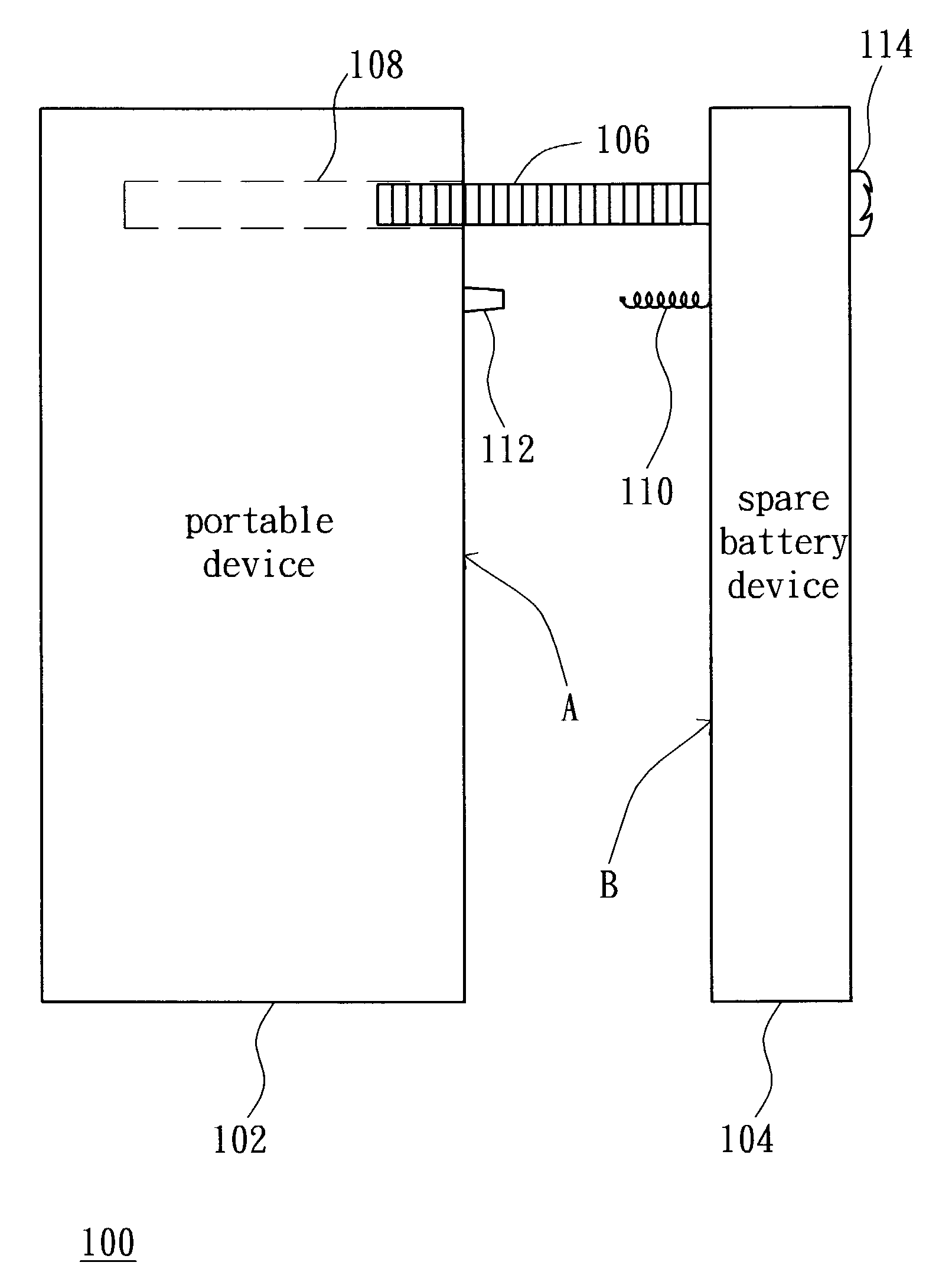
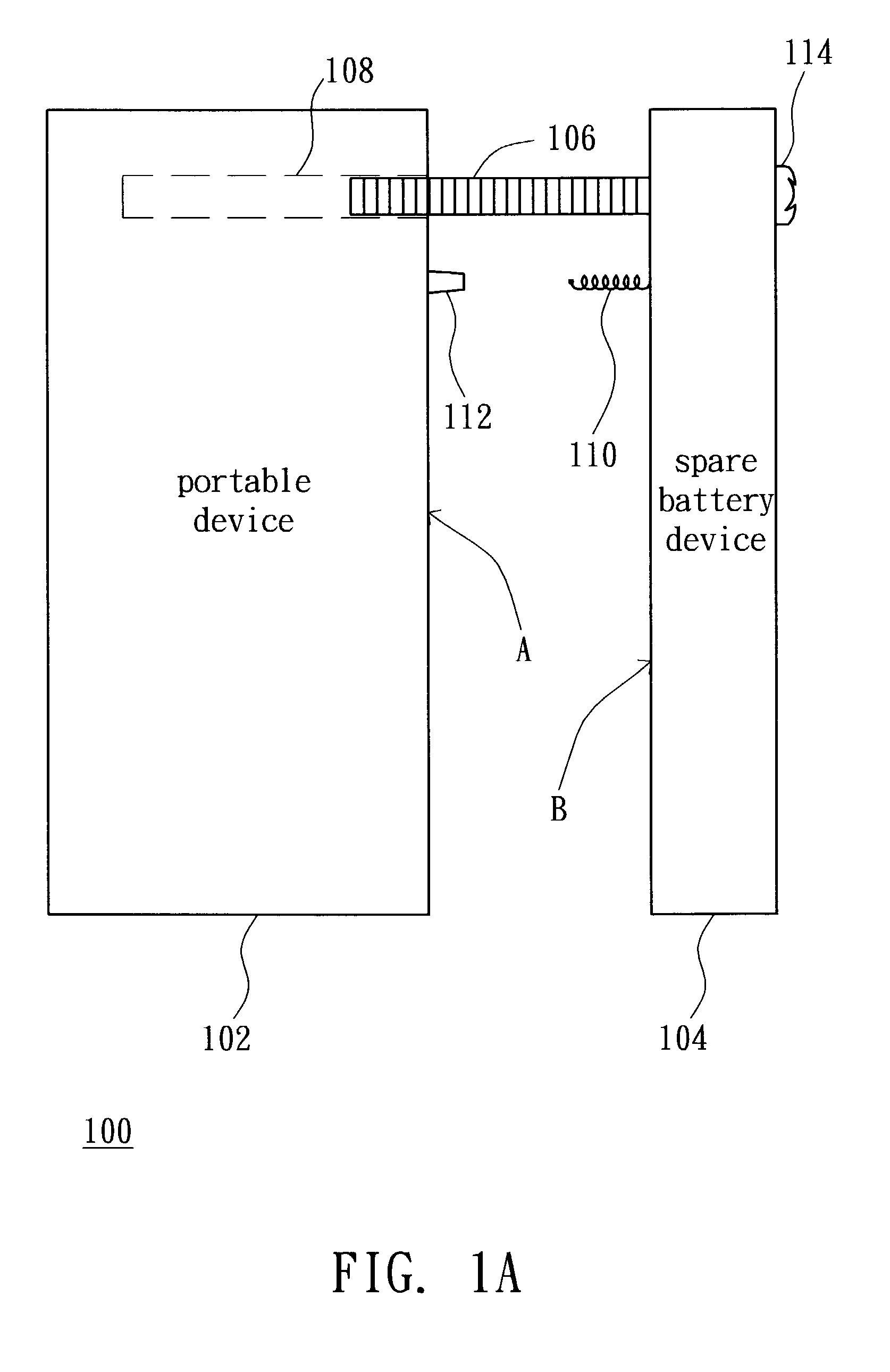
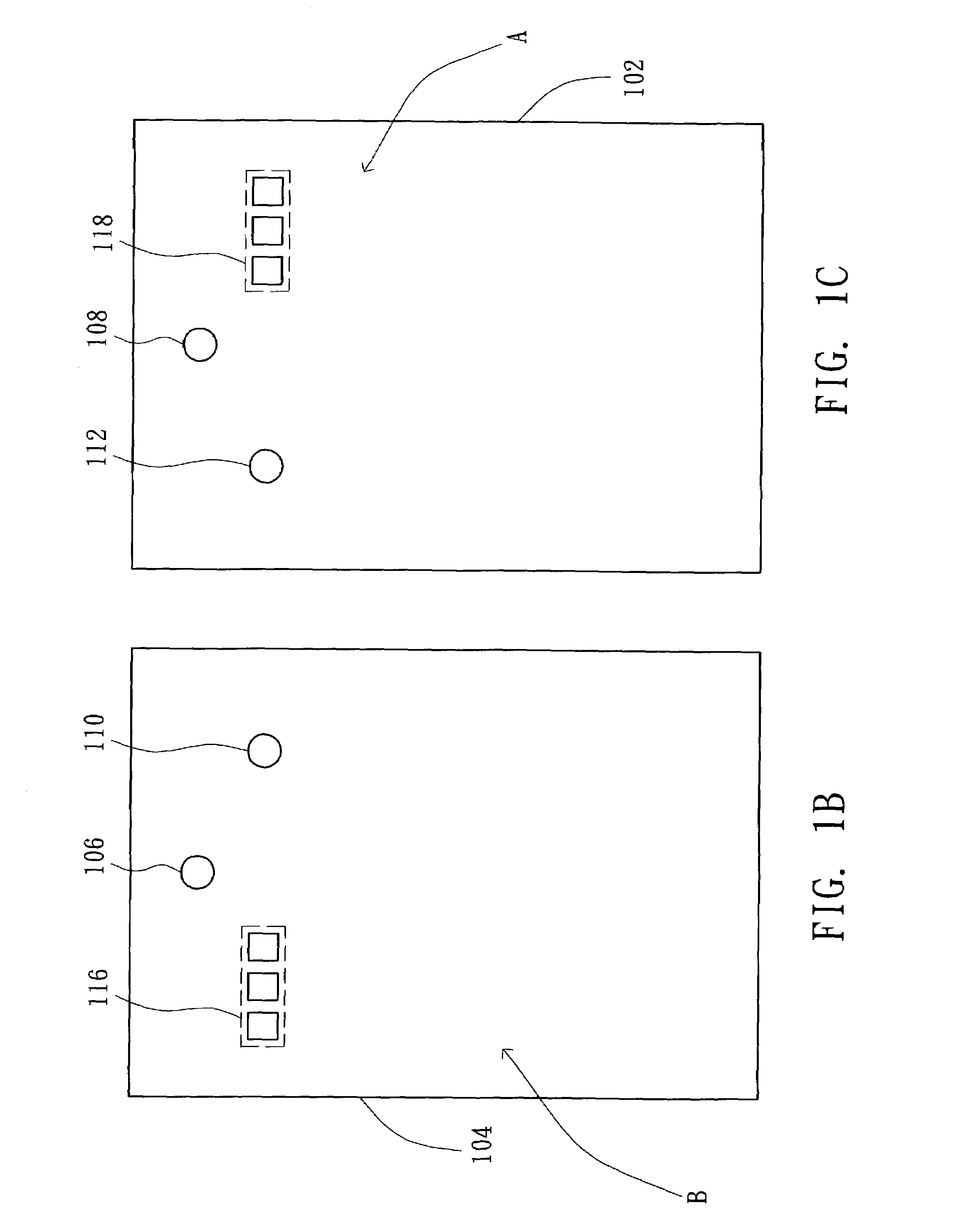
[0019]FIG. 1A illustrates a side view of a portable electronic system equipped with the spare battery device 100 according to the invention. The feature of the present invention is that only when the spare battery device 104 physically coupled to the portable device 102, which means that the spare battery device 104 is used as the power source of the portable device 102, the storing power of the spare battery device 104 can be outputted to the portable device102. When the power of the presently used battery runs out, the user can conveniently use the spare battery device 104 as a new power source of the portable device 102. And it is not easy for the spare battery device 104 in the idle status to leak out the storing power due to the external factors. The spare battery device 104 includes a first fixer unit 106; and the portable device 102 includes a second fixer unit 108. The spare battery device 104 can be coupled to the portable device 102 by coupling the first fixer unit 106 and...


PUM

PropertyMeasurementUnit
conductiveaaaaaaaaaa
constant voltageaaaaaaaaaa
voltageaaaaaaaaaa

Abstract

A portable electronic system equipped with a spare battery device. The portable electronic system includes a spare battery device and a portable device. The spare battery device includes a first fixer unit, a power storage unit and a sensory control unit. The sensory control unit further includes a constant voltage source, a resistor, a resilient object, output contact pads, and a control unit. The portable device includes a second fixer unit, a covering, and input contact pads. By adjusting the coupling relationship between the first fixer unit and the second fixer unit, each output contact pad can be coupled to the associated input contact pads; and the control unit is for controlling output power of the spare battery device.

Description

[0001]This application incorporates by reference Taiwan application Serial No. 090124764, filed Oct. 5, 2001.BACKGROUND OF THE INVENTION[0002]1. Field of the Invention[0003]This invention relates to a portable electronic system, and more particularly to a portable electronic system equipped with a spare battery device.[0004]2. Description of the Related Art[0005]The rapid development of digital electronic products makes people's life more convenient. And a lot of portable devices, such as mobile phones, notebooks, or Personal Digital Assistance (PDA), and so on, have been developed rapidly. It highly promotes the convenience of people's life and the efficiency of work. Portable devices, in the circumstance without an external power source, totally rely on batteries to supply the necessary operating power. It is, therefore, very important for the portable devices to have a stable power source supplied.[0006]When a battery has been used for a certain period of time, the battery will n...

Claims


Application Information

Patent Timeline
Patent Type & Authority Patents(United States)
IPC IPC(8): H04B1/38H04M1/00H02J9/00H01M10/44H02J7/00
CPCH02J7/0045H02J7/0063H02J7/007182
Inventor LIN, CHIEN-MIN
Owner HTC CORP
Why Eureka
Try Eureka