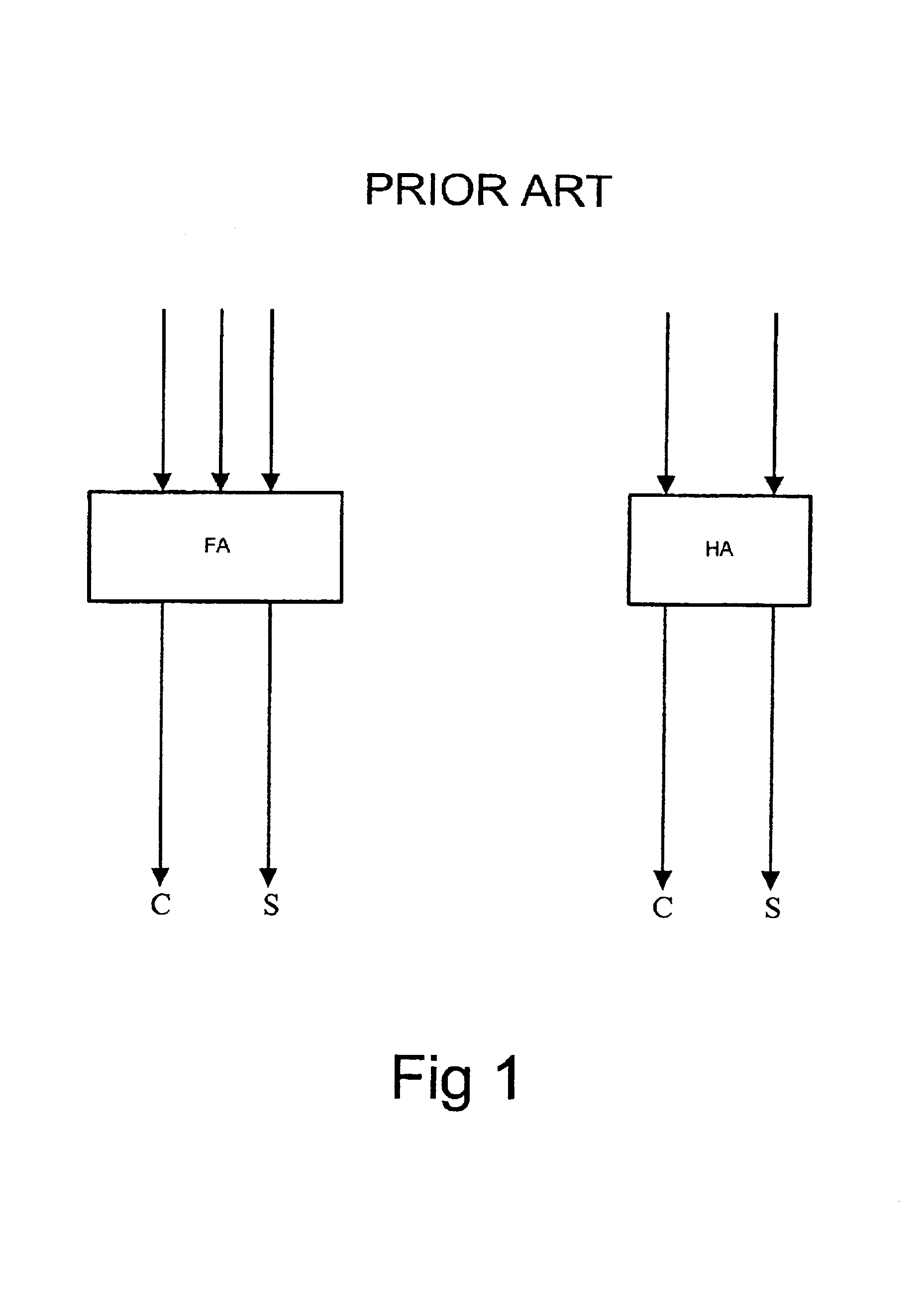
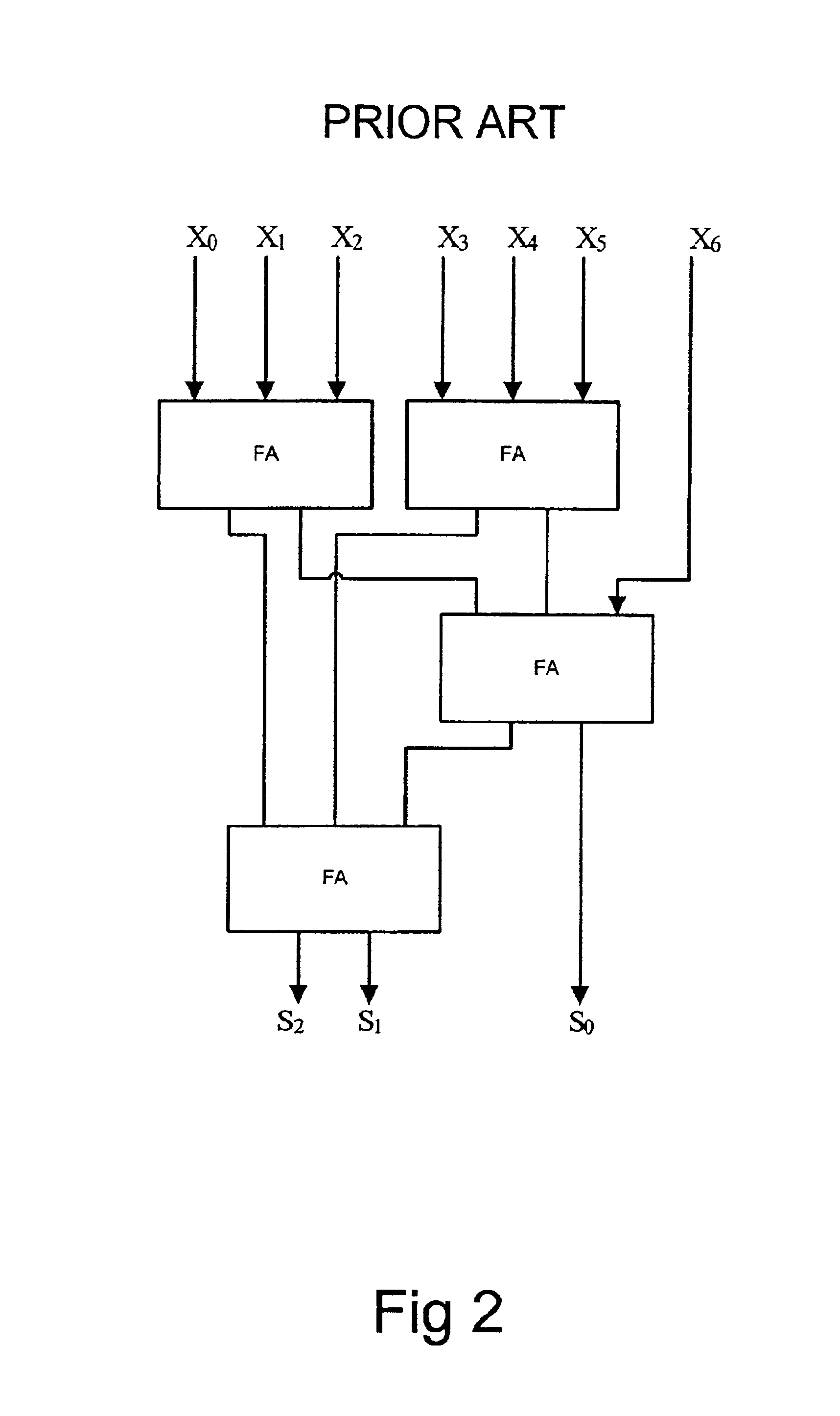
Parallel counter and a logic circuit for performing multiplication
a logic circuit and parallel counter technology, applied in the field of parallel counters and digital electronic devices performing binary logic, can solve the problem of large area increase, and achieve the effect of fast inverting logic gates
- Summary
- Abstract
- Description
- Claims
- Application Information
AI Technical Summary
Benefits of technology
Problems solved by technology
Method used
Image

Examples
first embodiment
[0116]In accordance with the present invention the parallel counter of each output is generated using a symmetric function using exclusive OR logic.
[0117]Let the parallel counter have n inputs X1, . . . Xn and t+1 outputs St, St−1, . . . S0. S0 is the least significant bit and St is the most significant bit. For all i from 0 to t,
Si=EXOR—n—2i(X1, X2, . . . Xn).
[0118]It can thus be seen that for a seven bit input i.e. n=7, i will have values of 0, 1 and 2. Thus to generate the output S0 the function will be EXOR—7—1, to generate the output S1 the function will be EXOR—7—2 and to generate the output S2 the function will be EXOR—7—4. Thus for the least significant bit the set size (k) is 1, for the second bit the set size is 2 and for the most significant bit the set size is 4. Clearly the logic required for the more significant bits becomes more complex and thus slower to implement.
second embodiment
[0119]Thus in accordance with the present invention, the most significant output bit is generated using a symmetric function using OR logic.
[0120]This is more practical since OR_n_k functions are faster than EXOR_n_k functions. For the most significant output bit
Sk=OR—n—2t(X1, X2, . . . Xn).
[0121]In particular, with a seven-bit input
S2=OR—7—4(X1, X2, X3, X4, X5, X6, X7).
[0122]Thus in this second embodiment of the present invention the most significant bit is generated using symmetric functions using OR logic whereas the other bits are generated using symmetric functions which use exclusive OR logic.
third embodiment
[0123]A third embodiment will now be described in which intermediate bits are generated using symmetric functions using OR logic.
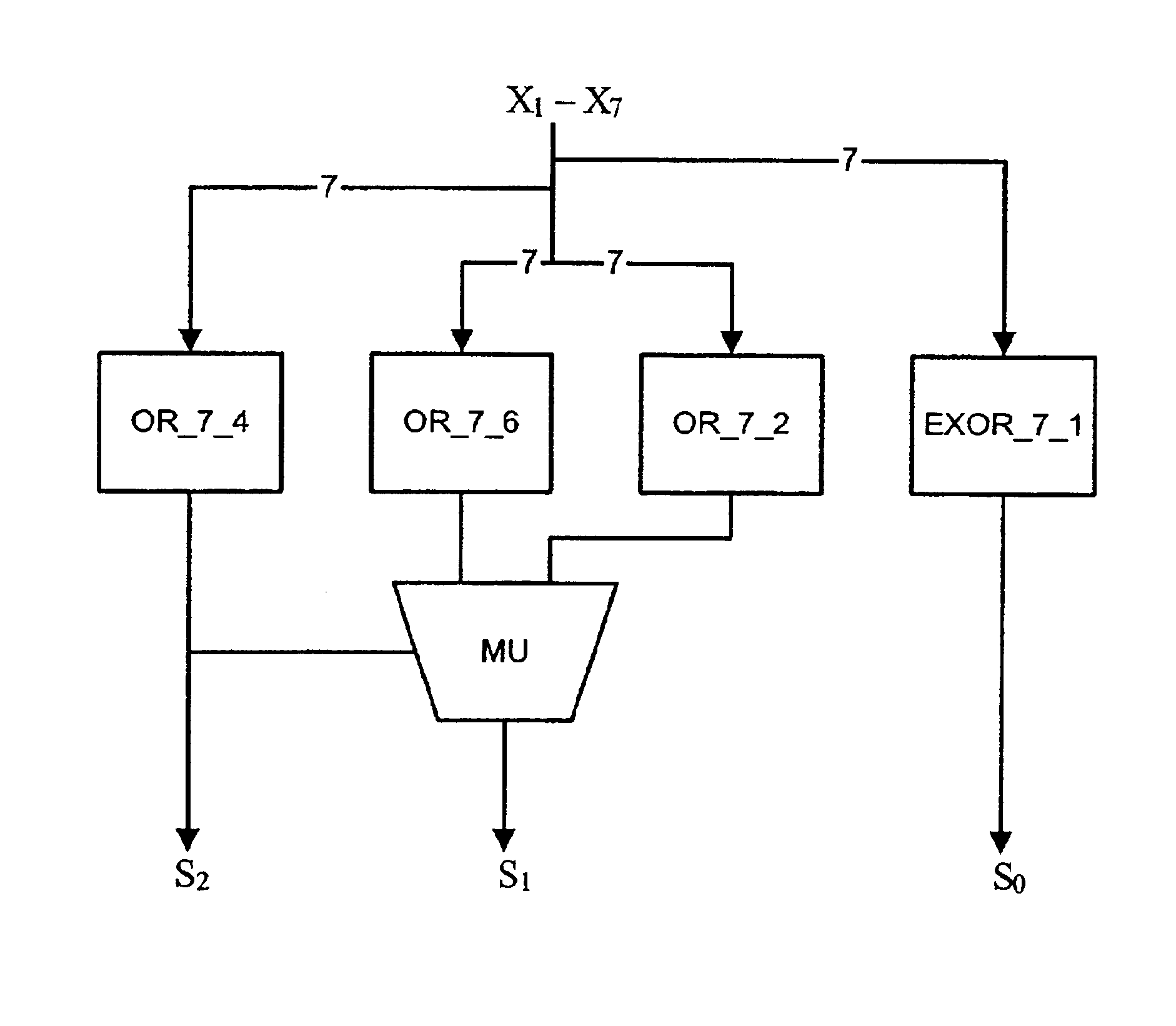
[0124]An arbitrary output bit can be expressed using OR_n_k functions if one knows bits that are more significant. For instance, the second most significant bit is given by
St−1=(StOR—n—2t+2t−1)((St)OR—n—2t−1).
[0125]In particular, with a seven-bit input
S1=(S2OR—7—6(X1, X2, X3, X4, X5, X6, X7))((S2)OR—7—2(X1, X2, X3, X4, X5, X6, X7)).
[0126]A further reduction is
S1=OR—7—6(X1, X2, X3, X4, X5, X6, X7)((S2)OR—7—2(X1, X2, X3, X4, X5, X6, X7)).
[0127]A multiplexer MU, shown in FIG. 3, implements this logic. It has two inputs X0, X1, a control C, and an output Z determined by the formula
Z=(CX1)((C)X0).
[0128]It is not practical to use either EXOR_n_k functions or OR_n_k functions exclusively. It is optimal to use OR_n_k functions for a few most significant bits and EXOR_n_k functions for the remaining bits. The fastest, in TSMC.25, parallel counter with 7 inputs is s...
PUM
 Abstract
Description
Claims
Application Information